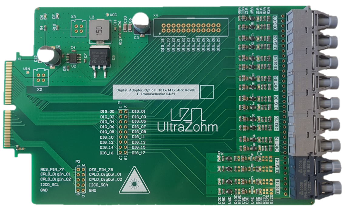
Digital Optical 14Tx4Rx Rev06
Functionality
Transmits up to 14 optical signals, e.g. gate signals.
Receives up to 4 optical signals, e.g. error signals.
LEDs on PCB signaling the state of the transmitter/receiver
Logic table
The underlying logic is that
Logic HIGH = LED/Transmitter/Receiver ON
Logic LOW = LED/Transmitter/Receiver OFF
Transmitter Logic
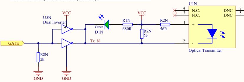
GATE |
Node Tx_N |
Transmitter LED U1 |
LED D1 |
|---|---|---|---|
LOW |
HIGH |
OFF |
OFF |
HIGH |
LOW |
ON |
ON |
Receiver Logic
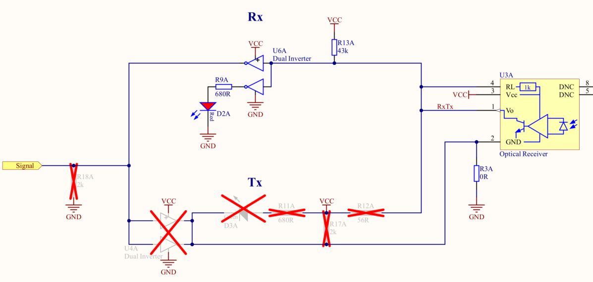
Receiver Diode U3 |
Node RxTx |
Signal |
LED D2 |
|---|---|---|---|
Light OFF |
HIGH |
LOW |
OFF |
Light ON |
LOW |
HIGH |
ON |
Before first use
Soldering
Solder in up to
14 optical transmitters: Broadcom HFBR-1521Z
4 optical receiver: Broadcom HFBR-2521Z
Please refer to this page for detailed Soldering instructions.
Note
Note that transmitters and receivers with even numbers are on the top side, starting to count from 0, to match with Vivado vector logic. While the uneven numbers are on the bottom side.
Program CPLDs
Program CPLDs with firmware, see Programming the CPLD for details. Note, that the signals are simply passed through the CPLD. Optionally, additional functionality can be implemented in the CPLD, e.g. checking for invalid switching combinations or introducing a dead time.
Additional features
Manual rework allows to exchange the 4 receiver channels to 4 transmitter channels, resulting in up to 18 transmitter channels, check Schematic and Assembly Drawing at the end of this page for the necessary changes.
Known issues
No known issues
Compatibility
Only compatible with CarrierBoard Rev04 and later, since the edge-connector has no chamfer (angle).
Slots D1 to D4 can be used without limitations, if CPLD is programmed correctly
Optical Cables
Optical Cables of type HFBR-RNSxxxZ are tested and recommended for transmitting the optical signals. The xxx determines the length of the cable in meters.
References
Designed by
Eugen Romanschenko (TUM), Eyke Liegmann (TUM) in 04/2021