Six-phase CIL Example
On this page, a description of a six-phase PMSM CIL model will be given, using the respective UZ IP-Cores.
Vivado
In this example, PWM blocks have been placed individually for the CIL. Alternatively, the PWM blocks from the standard model can be used. The outputs of the PWM blocks are combined with a Concat block and routed to the inverter’s gate inputs. Their voltage outputs are connected with the respective inputs of the Transformation IP-core, whose current outputs are fed back to the inverters. The transformation’s transformed output is connected with the PMSM, while the PMSM’s rotor angle and current outputs are connected with the Transformation. The trigger and refresh signals of the Transformation are connected with the RS-Flip-Flop as shown below.
Note
To simplify the usage of the CIL and to reduce possible errors, a tcl script was created, that places all necessary IP-Cores automatically and connects them. To use this, open the Vivado block design in a clean project and run the following commands seperately in the TCL-console. “cd [ get_property DIRECTORY [current_project] ]” “source ../../docs/source/mpsoc/ip_cores/uz_cil_pmsm/uz_cil_examples/sixphase_cil.tcl”
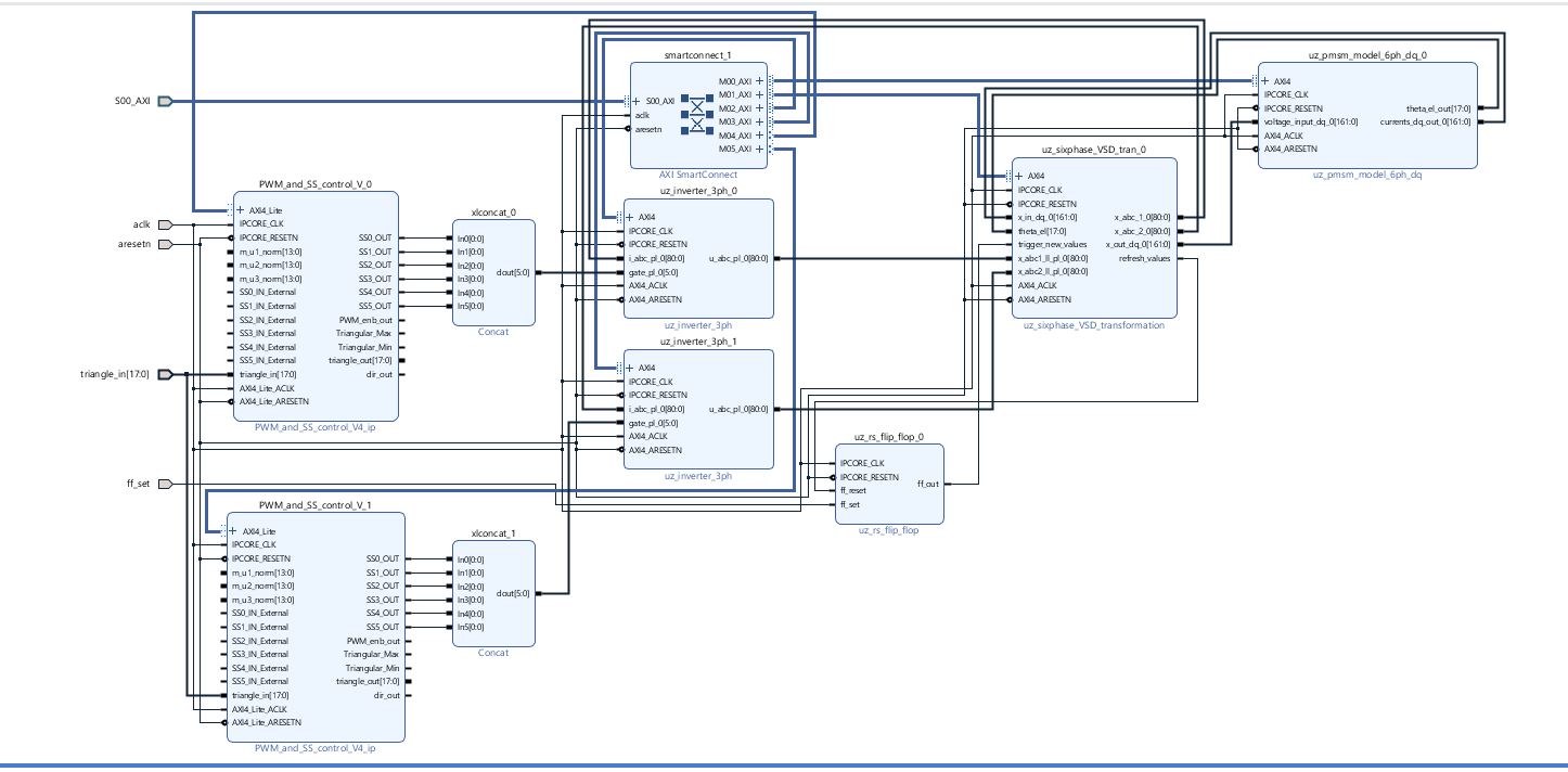
Fig. 163 Vivado setup
All individual connections of each IP-core are shown in the table below.
Typ |
Port name |
Target IP-core |
Target port name |
|---|---|---|---|
Transformation |
|||
In |
AXI4 |
smartconnect_1 |
M01_AXI |
In |
x_in_dq |
uz_pmsm_model_6ph_dq |
currents_dq_out |
In |
theta_el |
uz_pmsm_model_6ph_dq |
theta_el_out |
In |
trigger_new_values |
uz_rsflip_flop |
ff_out |
In |
x_abc1_ll_pl |
uz_inverter_3ph_0 |
u_abc_pl |
In |
x_abc2_ll_pl |
uz_inverter_3ph_1 |
u_abc_pl |
Out |
x_abc_1 |
uz_inverter_3ph_0 |
i_abc_pl |
Out |
x_abc_2 |
uz_inverter_3ph_1 |
i_abc_pl |
Out |
x_out_dq |
uz_pmsm_model_6ph_dq |
voltage_input_dq |
Out |
refresh_values |
uz_rs_flip_flop |
ff_reset |
PMSM |
|||
In |
AXI4 |
smartconnect_1 |
M00_AXI |
In |
voltage_input_dq |
uz_sixphase_VSD_tran |
x_out_dq |
Out |
theta_el_out |
uz_sixphase_VSD_tran |
theta_el |
Out |
currents_dq_out |
uz_sixphase_VSD_tran |
x_in_dq |
PWM 1/2 |
|||
In |
AXI4_Lite |
smartconnect_1 |
M0[4/5]_AXI |
In |
triangle_in |
../uz_digital_adapter/D1_adapter/Gates/PWM_and_SS_control_V0 |
triangle_out |
Out |
SS[0-5]_OUT |
uz_inverter_3ph_[1/2] |
gate_pl (use Concat) |
Inverter 1/2 |
|||
In |
AXI4 |
smartconnect_1 |
M0[2/3]_AXI |
In |
i_abc_pl |
uz_sixphase_VSD_tran |
x_abc_[1/2] |
In |
gate_pl |
PWM_and_SS_control_V[1/2] |
SS[0-5]_OUT (use concat) |
Out |
u_abc_pl |
uz_sixphase_VSD_tran |
x_abc[1/2]_ll_pl |
Vitis
Each IP-core is initialized in main.c, as well as a pointer with the respective type.
The init functions are called during the init process of all IP-cores.
...
// includes
#include "IP_Cores/uz_pmsm_model_6ph_dq/uz_pmsm_model6ph_dq.h"
#include "IP_Cores/uz_pmsm6ph_transformation/uz_pmsm6ph_transformation.h"
#include "IP_Cores/uz_inverter_3ph/uz_inverter_3ph.h"
#include "IP_Cores/uz_PWM_SS_2L/uz_PWM_SS_2L.h"

// PMSM
uz_pmsm_model6ph_dq_t *pmsm = NULL;
struct uz_pmsm_model6ph_dq_config_t cil_pmsm_comfig = {
    .base_address = XPAR_UZ_USER_UZ_PMSM_MODEL_6PH_DQ_0_BASEADDR,
    .ip_core_frequency_Hz = 100000000.0f,
    .polepairs = 4.0f,
    .r_1 = 0.3f,
    .inductance.d = 0.003f,
    .inductance.q = 0.003f,
    .inductance.x = 2.00e-03f,
    .inductance.y = 4.00e-03f,
    .inductance.z1 = 5.00e-03f,
    .inductance.z2 = 6.00e-03f,
    .psi_pm = 0.0075f,
    .friction_coefficient = 0.001f,
    .coulomb_friction_constant = 0.001f,
    .inertia = 0.001f,
    .simulate_mechanical_system = true,
    .switch_pspl = false};

// Transformation
uz_pmsm6ph_transformation_t *transformation = NULL;
struct uz_pmsm6ph_config_t cil_transformation_config = {
  .base_address = XPAR_UZ_USER_UZ_SIXPHASE_VSD_TRAN_0_BASEADDR,
    .ip_core_frequency_Hz = 100000000.0f};

// Inverter
uz_inverter_3ph_t *inverter1 = NULL;
uz_inverter_3ph_t *inverter2 = NULL;
struct uz_inverter_3ph_config_t cil_inverter1_config = {
    .base_address = XPAR_UZ_USER_UZ_INVERTER_3PH_0_BASEADDR,
    .ip_core_frequency_Hz = 100000000.0f,
    .switch_pspl_abc = false,
    .switch_pspl_gate = false,
    .udc = 100.0f};
struct uz_inverter_3ph_config_t cil_inverter2_config = {
    .base_address = XPAR_UZ_USER_UZ_INVERTER_3PH_1_BASEADDR,
    .ip_core_frequency_Hz = 100000000.0f,
    .switch_pspl_abc = false,
    .switch_pspl_gate = false,
    .udc = 100.0f};

// PWM (optional, only necessary if default PWM blocks are not used)
uz_PWM_SS_2L_t *PWM1 = NULL;
uz_PWM_SS_2L_t *PWM2 = NULL;
struct uz_PWM_SS_2L_config_t cil_pwm1_config = {
  .base_address= XPAR_UZ_USER_PWM_AND_SS_CONTROL_V_0_BASEADDR,
  .ip_clk_frequency_Hz=100000000.0f,
  .Tristate_HB1 = false,
  .Tristate_HB2 = false,
  .Tristate_HB3 = false,
  .min_pulse_width = 0.01f,
  .PWM_freq_Hz = UZ_PWM_FREQUENCY,
  .PWM_mode = normalized_input_via_AXI,
  .PWM_en = true,
  .use_external_counter = true};
struct uz_PWM_SS_2L_config_t cil_pwm2_config = {
  .base_address= XPAR_UZ_USER_PWM_AND_SS_CONTROL_V_1_BASEADDR,
  .ip_clk_frequency_Hz=100000000.0f,
  .Tristate_HB1 = false,
  .Tristate_HB2 = false,
  .Tristate_HB3 = false,
  .min_pulse_width = 0.01f,
  .PWM_freq_Hz = UZ_PWM_FREQUENCY,
  .PWM_mode = normalized_input_via_AXI,
  .PWM_en = true,
  .use_external_counter = true};

// PI controllers, only necessary for example, you can use your own controller
#include "uz/uz_piController/uz_piController.h"
const struct uz_PI_Controller_config PI_config = {
  .Kp = 1250.0f,
  .Ki = 78250.0f,
  .samplingTime_sec = 0.0001f,
  .upper_limit = 100.0f,
  .lower_limit = -100.0f};
uz_PI_Controller *PI_d_current=NULL;
uz_PI_Controller *PI_q_current=NULL;
...
int main(void)
{
  ...
  case init_ip_cores:
    // init IP-cores
        pmsm = uz_pmsm_model6ph_dq_init(cil_pmsm_comfig);
    transformation = uz_pmsm6ph_transformation_init(cil_transformation_config);
    inverter1 = uz_inverter_3ph_init(cil_inverter1_config);
    inverter2 = uz_inverter_3ph_init(cil_inverter2_config);
    PWM1 = uz_PWM_SS_2L_init(cil_pwm1_config);
    PWM2 = uz_PWM_SS_2L_init(cil_pwm2_config);
    // init PI-controllers
    PI_d_current = uz_PI_Controller_init(PI_config);
    PI_q_current = uz_PI_Controller_init(PI_config);
  ...
To use the CIL setup, the IP-core’s pointers have to be imported to the isr.c.
Also, variables to store the outputs of the CIL model are defined.
In this example, a PI controller is used to control the PMSM.
The usage is not necessary and the respective parts can be disregarded if other controllers are used.
In the end, the duty cycles are given to the defined PWM modules.
Depending on the used controller, this might not be necessary.
...
// Data for PMSM
#include "../IP_Cores/uz_pmsm_model_6ph_dq/uz_pmsm_model6ph_dq.h"
extern uz_pmsm_model6ph_dq_t *pmsm;
float omega_mech = 100.0f;
float load_torque = 0.0f;
struct uz_pmsm_model6ph_dq_outputs_general_t pmsm_output = {0};

// Data for Transformation
#include "../IP_Cores/uz_pmsm6ph_transformation/uz_pmsm6ph_transformation.h"
#include "../uz/uz_Transformation/uz_Transformation.h"
extern uz_pmsm6ph_transformation_t *transformation;
uz_6ph_abc_t transformation_currents_abc = {0};
float theta_el = 0.0f;

// Data for PI
#include "../uz/uz_piController/uz_piController.h"
extern uz_PI_Controller *PI_d_current;
extern uz_PI_Controller *PI_q_current;
uz_6ph_dq_t transformed_currents = {0};
uz_3ph_dq_t setp_currents = {0};
uz_6ph_dq_t output_voltage_dq = {0};
uz_6ph_abc_t out_voltage_abc = {0};
uz_3ph_abc_t out_voltage_abc1 = {0};
uz_3ph_abc_t out_voltage_abc2 = {0};

// Data for PWM
#include "../IP_Cores/uz_PWM_SS_2L/uz_PWM_SS_2L.h"
#include "../uz/uz_FOC/uz_FOC.h"
extern uz_PWM_SS_2L_t *PWM1;
extern uz_PWM_SS_2L_t *PWM2;
float V_dc_volts = 500.0f;
struct uz_DutyCycle_t duty_cycle_sys1 = {0};
struct uz_DutyCycle_t duty_cycle_sys2 = {0};
...
void ISR_Control(void *data)
{
  ...
  // CIL
  uz_pmsm_model6ph_dq_set_inputs_general(pmsm,omega_mech,load_torque);                                          // set omega and load torque (only one active)
  pmsm_output = uz_pmsm_model6ph_dq_get_outputs_general(pmsm);                                                  // read outputs from PMSM
  transformation_currents_abc = uz_pmsm6ph_transformation_get_currents(transformation);                         // read current from transformation
  theta_el = uz_pmsm6ph_transformation_get_theta_el(transformation);                                            // read theta from transformation

  // Controller
  transformed_currents = uz_transformation_asym30deg_6ph_abc_to_dq(transformation_currents_abc, theta_el);      // transform currents
  output_voltage_dq.d = uz_PI_Controller_sample(PI_d_current, setp_currents.d, transformed_currents.d, false);  // sample d-current controller
  output_voltage_dq.q = uz_PI_Controller_sample(PI_q_current, setp_currents.q, transformed_currents.q, false);  // sample q-current controller
  out_voltage_abc = uz_transformation_asym30deg_6ph_dq_to_abc(output_voltage_dq, theta_el);                     // transform setpoint voltages to phase voltages
  out_voltage_abc1.a = out_voltage_abc.a1;                                                                      // seperate voltages into 3ph structs
  out_voltage_abc1.b = out_voltage_abc.b1;
  out_voltage_abc1.c = out_voltage_abc.c1;
  out_voltage_abc2.a = out_voltage_abc.a2;
  out_voltage_abc2.b = out_voltage_abc.b2;
  out_voltage_abc2.c = out_voltage_abc.c2;

  // Duty Cycles
  duty_cycle_sys1 = uz_FOC_generate_DutyCycles(out_voltage_abc1, V_dc_volts); //create Duty-Cycles for subsets
  duty_cycle_sys2 = uz_FOC_generate_DutyCycles(out_voltage_abc2, V_dc_volts); //create Duty-Cycles for subsets
  uz_PWM_SS_2L_set_duty_cycle(PWM1, duty_cycle_sys1.DutyCycle_U, duty_cycle_sys1.DutyCycle_V, duty_cycle_sys1.DutyCycle_W);
  uz_PWM_SS_2L_set_duty_cycle(PWM2, duty_cycle_sys2.DutyCycle_U, duty_cycle_sys2.DutyCycle_V, duty_cycle_sys2.DutyCycle_W);
  ...