Resolver PL Interface#
This IP Core is designed as an add-on to the Resolver Interface uz_resolverIP. There are three intended use-cases.
1. This IP Core provides angle and speed outputs in fixed-point SI values in the FPGA for control applications in the FPGA. It handles all dependencies to the number of polepairs of the resolver and the machine, as well as angle zero point offset between resolver and machine. The electrical and mechanical angle are limited to the range of \(0..2{\pi}\).
2. For control algorithms in the processor, saving every \({\mu}s\) of calculation effort is sometimes crucial. Therefore most of the software driver
functionality of the uz_resolverIP can be “outsourced” into this IP Core. Therefore, no calculations from raw values of the resolver with respect
to polepairs and offsets will cause workload in the processor, just reading angles and speeds via AXI is necessary.
3. Sometimes you might have a unfavorable combination of resolver polepairs and machine polepairs. E.g. machine polepairs \(p_m=5\) and resolver polepairs \(p_r=2\) results in a fractional ratio between mechanical and electrical revolutions of the machine and the resolver. A strategy to deal with this is to convert the resolver revolutions to one mechanical revolution of the machine and derive electrical revolutions from there. This comes at the cost of loosing absolute position information in the beginning and requires a defined mechanical init position of the machine at startup. The IP Core handles these complicated sounding calculations. The user just has to provide all the polepair numbers and has to define the rotational position of the machine at the testbench at startup. Subsequently, all angle and speed information can be used as usual by reading them via AXI.
Interface Definition#
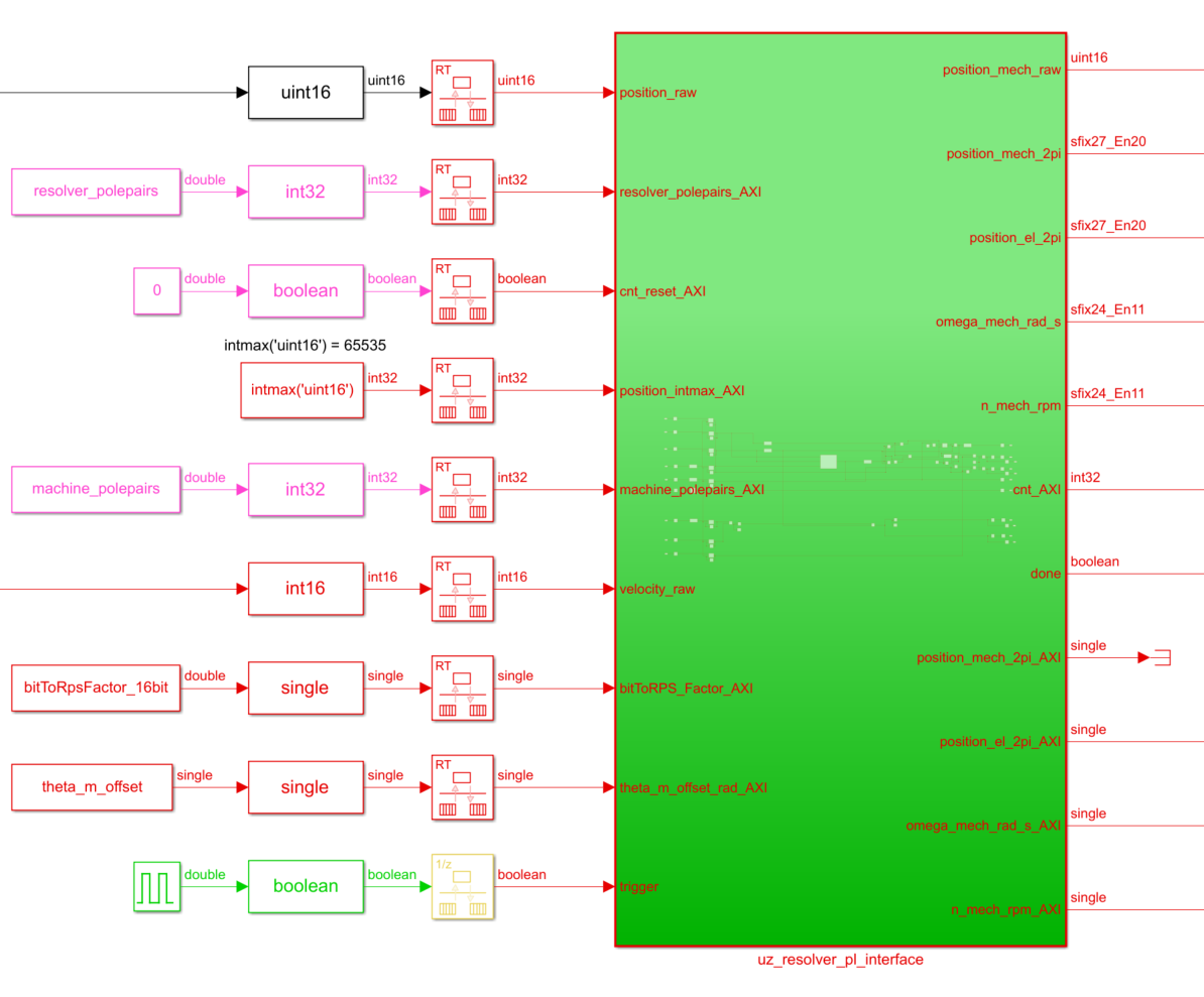
Fig. 366 Simulink source of uz_resolver_pl_interface#
Table Interface of resolver_pl_interface IP-Core lists all input and output ports (AXI and external port) that are present in the IP-Core.
Port Name |
Port Type |
Data Type |
Target Platform Interfaces |
Range |
Unit |
Function |
|---|---|---|---|---|---|---|
PL ports |
||||||
position_raw |
Input |
uint16_t |
External Signal |
0..65535 |
1 |
raw value of angle |
velocity_raw |
Input |
int16_t |
External Signal |
-32768..32767 |
1 |
raw value of speed |
trigger |
Input |
bool |
External Signal |
false..true |
1 |
trigger calculations |
position_mech_raw |
Output |
uint16_t |
External Signal |
0..65535 |
1 |
raw mechanical position (theta_m_offset_rad not respected) |
position_mech_2pi |
Output |
sfix27_En20 |
External Signal |
0..2pi |
rad |
mechanical position in rad |
position_el_2pi |
Output |
sfix27_En20 |
Exernal Signal |
0..2pi |
rad |
electrical position in rad |
omega_mech_rad_s |
Output |
sfix24_En11 |
External Signal |
-4096..4095.9995 |
rad/s |
mechanical speed in rad/s |
n_mech_rpm |
Output |
sfix24_En11 |
External Signal |
-4096..4095.9995 |
rounds per minute |
mechanical speed in rpm |
done |
Output |
bool |
External Signal |
false..true |
1 |
true if ip core calculations are finished |
AXI4-Lite ports |
||||||
resolver_polepairs |
Input |
int32_t |
AXI4-Lite |
1..int32max |
1 |
polepairs of the resolver_polepairs |
cnt_reset |
Input |
bool |
AXI4-Lite |
false..true |
1 |
reset the internal revolution counter (is triggered once at init) |
position_intmax |
Input |
int32_t |
AXI4-Lite |
0..int32max |
1 |
represents the max possible raw value according to the resolution setting of the resolver (e.g. 65535 for 16bit) |
machine_polepairs |
Input |
int32_t |
AXI4-Lite |
1..int32max |
1 |
polepairs of the machine |
bitToRPS_Factor |
Input |
float |
AXI4-Lite |
>0..floatmax |
rounds per second/velocity_raw |
calculates speed in rounds per second from raw value |
theta_m_offset_rad |
Input |
float |
AXI4-Lite |
-2pi..0 |
rad |
mechanical offset between resolver zero and machine zero |
position_mech_2pi |
Output |
float |
AXI4-Lite |
0..2pi |
rad |
mechanical position in rad |
position_el_2pi |
Output |
float |
AXI4-Lite |
0..2pi |
rad |
electrical position in rad |
omega_mech_rad_s |
Output |
float |
AXI4-Lite |
+/- floatmax |
rad/s |
mechanical speed in rad/s |
n_mech_rpm |
Output |
float |
AXI4-Lite |
+/- floatmax |
rounds per minute |
mechanical speed in rpm |
Example Usage#
The following step-by-step description shall guide the user in order to properly implement the IP Core and the respective interface and software drivers.
Vivado Block Design#
First, the ip core has to be added to the block design in vivado:
Go to the place where the Resolver Interface IP Core
uz_resolverIPis located (e.g. inside the already existinguz_userhierarchy) in the block design.Add the Resolver PL Interface IP Core
uz_resolver_pl_interface.Connect the signals as shown below. Pay attention that
position_out_m,velocity_out_mandvalid_mare output signals of the Resolver Interface IP Core and serve as the inputs for all calculations inside theuz_resolver_pl_interfaceIP Core.Now the output ports
to your IPcan be used inside the FPGA block design. In parallel, the AXI4-Lite values are also available.
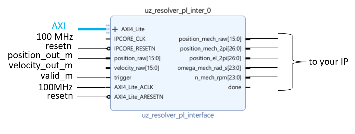
Fig. 367 IP Core in the Vivado block design#
Software driver#
For interacting with the IP Core, the following step-by-step example shows a way of implementing one instance of the software driver.
In Vitis, in the Baremetal project under the folder
hw_initcreate a new fileuz_resolver_pl_interface_init.cInclude necessary files and create
configandoutputstructs as well as an init function for one or more instances:
#include "../include/uz_resolver_pl_interface_init.h"
#include "../uz/uz_HAL.h"
#include "../uz/uz_global_configuration.h"
#include "xparameters.h"

struct uz_resolver_pl_interface_config_t resolver_pl_config_d2 = {
               .base_address = XPAR_UZ_USER_UZ_RESOLVER_PL_INTER_0_BASEADDR,
               .bitToRPS_factor = BIT_TO_RPS_FACTOR_16BIT,
               .ip_clk_frequency_Hz = 100000000,
               .machine_polepairs = 4,
               .position_intmax = 65535,
               .resolver_polepairs = 1,
               .theta_m_offset_rad = -0.3964f
};

struct uz_resolver_pl_interface_outputs_t resolver_pl_outputs_d2 = {
               .n_mech_rpm = 0.0f,
               .omega_mech_rad_s = 0.0f,
               .position_el_2pi = 0.0f,
               .position_mech_2pi = 0.0f,
               .revolution_counter = 0
};

uz_resolver_pl_interface_t* initialize_resolver_pl_d2(void){
       return (uz_resolver_pl_interface_init(resolver_pl_config_d2, resolver_pl_outputs_d2));
}
In the
includefolder, create a header fileuz_resolver_pl_interface_init.hInclude necessary files and the function prototype of your init routine:
#pragma once
#include "../IP_Cores/uz_resolver_pl_interface/uz_resolver_pl_interface.h"

uz_resolver_pl_interface_t* initialize_resolver_pl_d2(void);
In the Global_Data header file
globalData.h, include necessary header and add an object pointer of the respective type in theobject_pointer_tstruct:
...
#include "IP_Cores/uz_resolver_pl_interface/uz_resolver_pl_interface.h"
...

typedef struct{
...
uz_resolver_pl_interface_t* resolver_pl_d2;
...
}object_pointers_t;
In
main.c, initialize an instance of the driver and assign it to the object pointer structure in the Global_Data inside theinit_ip_corescase:
...
case init_ip_cores:
...
Global_Data.objects.resolver_pl_d2 = initialize_resolver_pl_d2();
...
break;
In
main.h, include your init header file#include "include/uz_resolver_pl_interface_init.h".In
isr.c, now you can read the AXI output values of the IP Core and use them e.g. for your control algorithm:
...
YourOutputStruct = uz_resolver_pl_interface_get_outputs(Global_Data.objects.resolver_pl_d2);
...
Driver reference#
-
typedef struct uz_resolver_pl_interface_t uz_resolver_pl_interface_t#
Data type for object uz_resolver_pl_interface.
-
struct uz_resolver_pl_interface_config_t#
Configuration struct for uz_resolver_pl_interface.
Public Members
-
uint32_t base_address#
Base address of the IP-Core
-
uint32_t ip_clk_frequency_Hz#
Clock frequency of the IP-Core
-
int32_t resolver_polepairs#
Polepairs of the resolver, only positive values >=1 are allowed
-
int32_t machine_polepairs#
Polepairs of the machine, only positive values >=1 are allowed
-
int32_t position_intmax#
Maximum representable int value for selected bit resolution, e.g. 2^16=65525 for 16bit resolution
-
float bitToRPS_factor#
value for calculating velocity raw value of resolverIP int rounds per second
-
float theta_m_offset_rad#
mechanical angle offset in rad between machine angle zero and resolver angle zero, only values <=0.0f & >=-2pi allowed
-
uint32_t base_address#
-
struct uz_resolver_pl_interface_outputs_t#
Output struct for uz_resolver_pl_interface.
Public Members
-
int32_t revolution_counter#
Not needed in regular operation, internal counter of the IP-Core, that is used to calculate correct electrical and mechanical angles if polepairs of resolver and machine result in a fractional rational number
-
float position_mech_2pi#
mechanical angle in rad, ranging from 0..2pi
-
float position_el_2pi#
electrical angle in rad, ranging from 0..2pi
-
float omega_mech_rad_s#
mechanical speed in rad per second
-
float n_mech_rpm#
mechanical speed in min^(-1)
-
int32_t revolution_counter#
-
uz_resolver_pl_interface_t *uz_resolver_pl_interface_init(struct uz_resolver_pl_interface_config_t config, struct uz_resolver_pl_interface_outputs_t outputs)#
Initializes an instance of the uz_resolver_pl_interface driver.
- Parameters:
config – Configuration values for the IP-Core
- Returns:
Pointer to initialized instance
-
void uz_resolver_pl_interface_set_config(uz_resolver_pl_interface_t *self)#
Writes the config from the struct into the IP-Core.
- Parameters:
self – Pointer to the instance
-
struct uz_resolver_pl_interface_outputs_t uz_resolver_pl_interface_get_outputs(uz_resolver_pl_interface_t *self)#
Updates and returns the AXI outputs of the IP-Core.
- Parameters:
self – Pointer to the instance
-
void uz_resolver_pl_interface_set_theta_m_offset_rad(uz_resolver_pl_interface_t *self, float theta_m_offset_rad)#
Writes new theta_m_offset_rad value into config and into the IP-Core.
- Parameters:
self – Pointer to the instance
theta_m_offset_rad – Mechanical angle offset in rad between machine angle zero and resolver angle zero, only values <=0.0f & >=-2pi allowed
-
void uz_resolver_pl_interface_reset(uz_resolver_pl_interface_t *self)#
Resets the internal revolution counter of the IP-Core, automatically done at init.
- Parameters:
self – Pointer to the instance