First steps with the UltraZohm#
Aim of the tutorial#
In this tutorial, the initial steps needed to get the UltraZohm running after cloning the repository are shown.
Requirements#
The following tutorial requires:
UltraZohm connected to your PC by Ethernet and USB (JTAG)
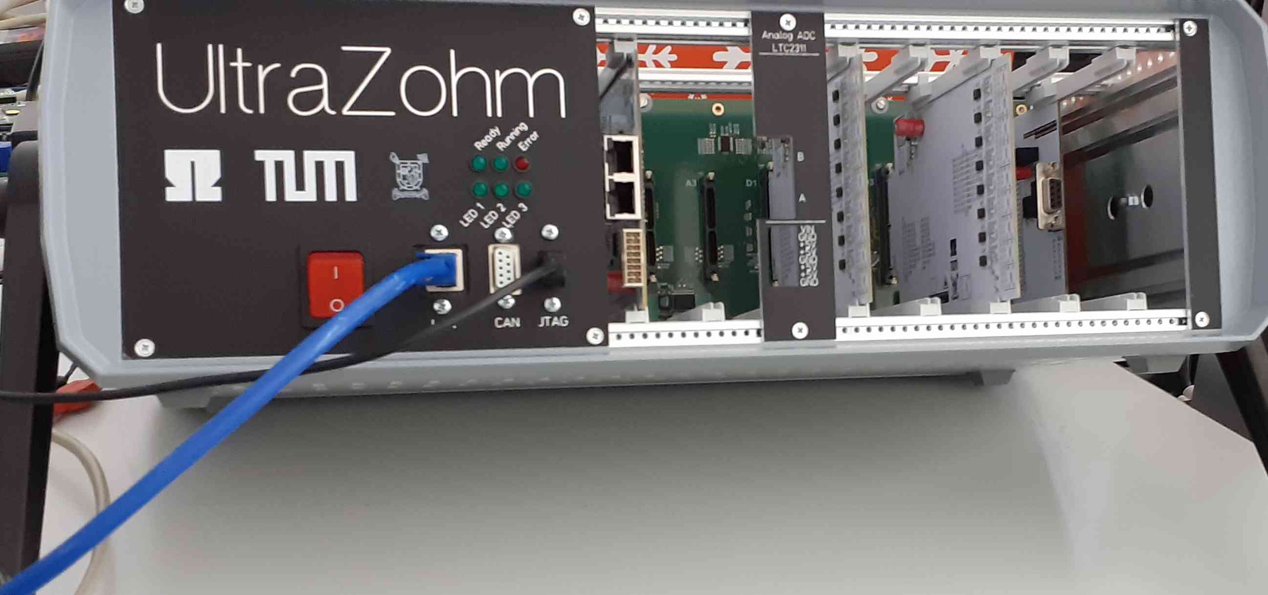
UltraZohm Setup#
The UltraZohm has to be connected to a PC by Ethernet and USB (JTAG programmer).
Initial steps#
Open the Git terminal inside the cloned UltraZohm repository, or alternatively do the following steps via your git client (e.g., Sourcetree (git GUI)).
Change your active branch from
maintodevelopby using the checkout keyword (e.g.,git checkout develop).The
developbranch is the current development branch with the latest merged changes made to the UltraZohm repository. Every new feature branch will be created from this point.The
mainbranch is the latest stable version.For further information, see Contribution Workflow.
Create a new local branch with an appropriate name (e.g., name_tutorial) on which the changes made throughout the tutorial will be made.
Warning
This branch is only used locally for the tutorials. Do not push any changes to the remote repository.
Start Vitis and open the workspace folder (
ultrazohm_sw/vitis/workspace) of the UltraZohm repository.Vitis is used to change the code for the Processor (PS). For example, if you want to run a control algorithm on the ARM-Cortex processors of the UltraZohm, you have to make changes in Vitis.
Vivado is used to change the programmable logic (PL), i.e., the FPGA of the Zynq UltraScale.
Review the contents of
uz_global_configuration.hbefore building the source codeThis file is the configuration file for the UltraZohm and has to be adjusted to your specific needs.
Change the
UZ_HARDWARE_VERSIONto the version of your UltraZohm.Note that on hardware revision 5 or newer, potential mismatches between the define and the actual hardware version are handled by the software.
See Global configuration for further details.
Build the project by clicking on the red highlighted hammer visible in Fig. 1.
Whenever changes have been made to the code base, this button has to be pressed.
If this button is not pressed after changes have been made, these changes can’t be flashed onto the UltraZohm, and the previously built binary is programmed (without the changes!).

Fig. 1 Building the workspace#
The build can fail, leading to errors as exemplarily depicted below.
Whenever you make changes to the codebase and the build leads to errors, they have to be fixed, otherwise, the UltraZohm cannot be flashed properly. This is because the errors stop the compiler from compiling the entire workspace.
While warnings do not prohibit the UltraZohm from working, they should be fixed nonetheless.
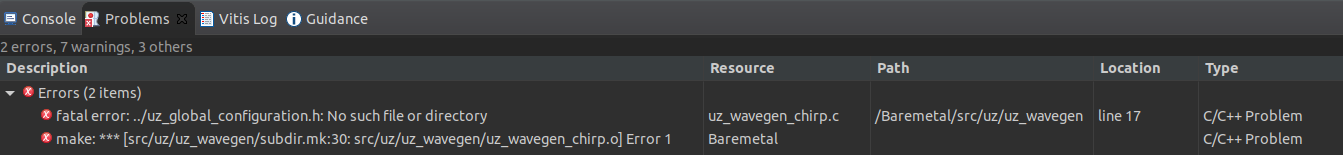
Fig. 2 Errors after building the workspace#
The build is successful.
Flash the UltraZohm by either pressing the run icon in the green highlighted area in Fig. 3 and select Debug Configurations…. Vitis will remember the last selection, which means that for a future flashing operation, the last debug config is already preselected.
Use the
Run_UltraZohmconfiguration for the debug/run selection.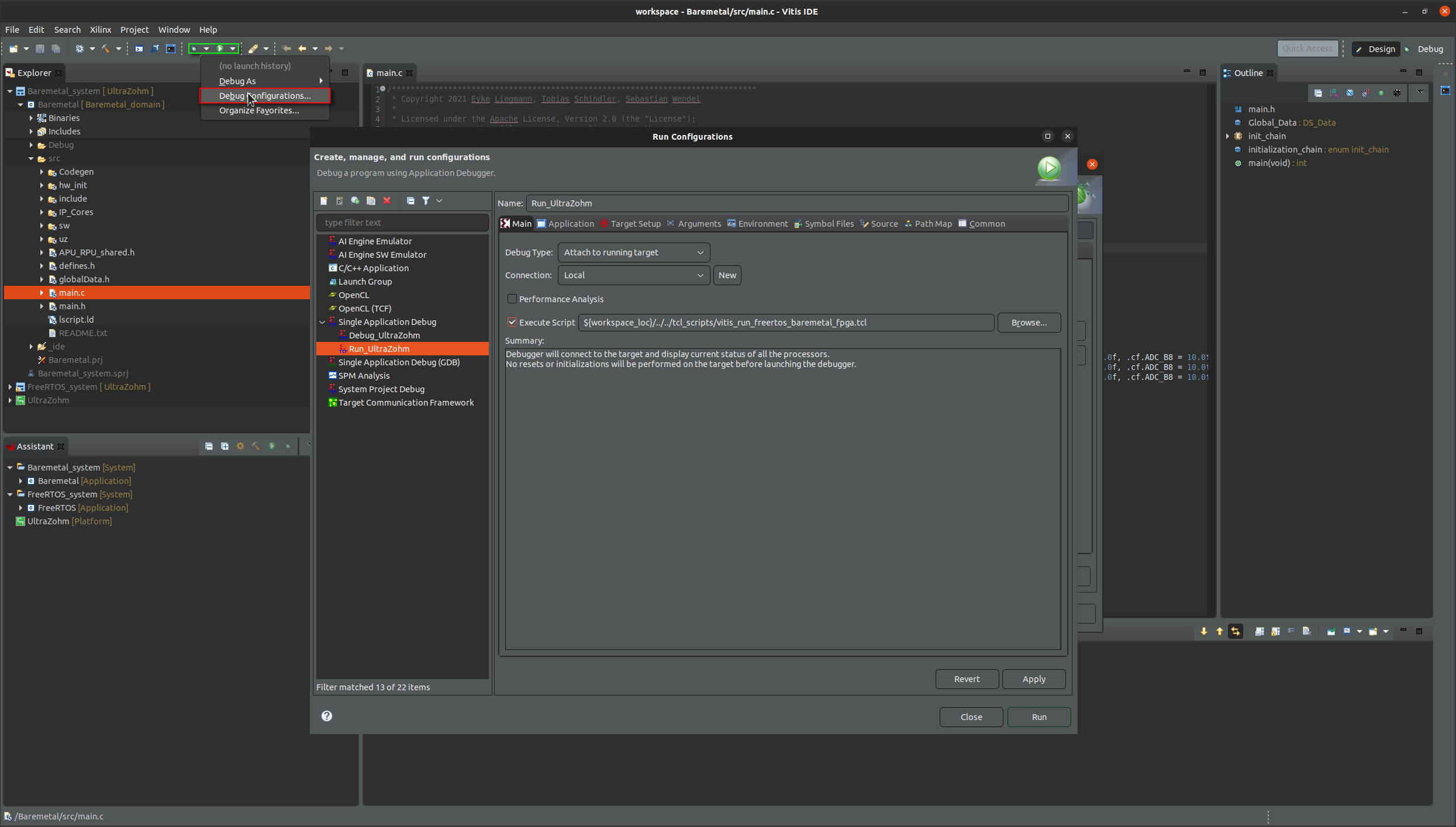
Fig. 3 Debug configuration in Vitis.#
If the flashing was successful, the Ready LED will blink slowly.
Make sure that you have configured your Ethernet-to-USB adapter according to this guide.
Start the uz_GUI in the folder
ultrazohm_sw/javascopeby double-clicking on theUZ_GUI.jarfile or executing thejavascope_run.batfile.Press the Connect button in the GUI. Now the GUI should be up and running.
If the connection was successful, the field to the left of the IP address is moving.
If nothing happens, check out the known issues section.
Five default channels are visible in the scope after pressing the sendSelectData (all) button.
To get the signals into the scope view, adjust the scaling of the first three channels.
Adjust the time base of the scope via the setTime button and the dropdown menu to
x10.FYI, the values for the channels theta_mech and ua are, in the default case, 0.
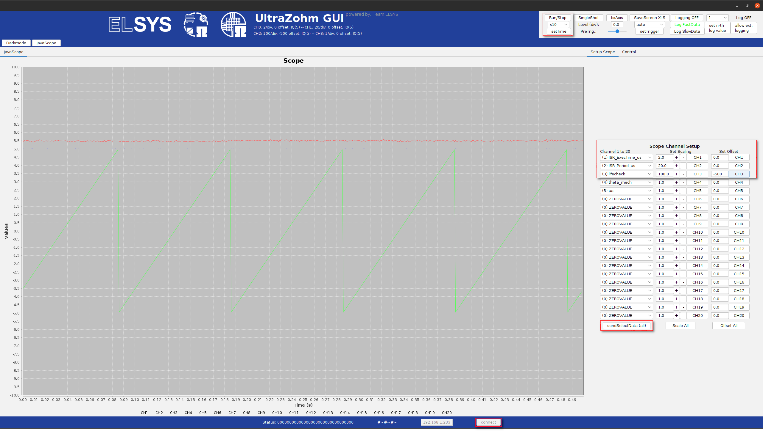
Fig. 4 Visible signals after GUI has been connected.#
Get familiar with the GUI by trying different things in the GUI. For further information, read the sections about the Setup Scope Page, Control Page, and Logging Panel.
In the next tutorial, changes will be made to the codebase, and the GUI will be customized.