First changes to the codebase#
Aim of the tutorial#
In this tutorial, a multi-instance module from the Waveform Generator library of the UltraZohm project will be used and the output displayed in the GUI.
Requirements#
The following tutorial requires:
Complete the tutorial First steps with the UltraZohm.
Guideline#
For the purpose of this tutorial, multiple instances of the Chirp wave will be used.
Open the
uz_global_configuration.hfile and look at the#define UZ_WAVEGEN_CHIRP_MAX_INSTANCESnumber.Currently, two instances of this module are allowed. This means that the
uz_wavegen_chirp_initfunction can only be called twice, before an assertion stops the processor.This is done to ensure a proper static memory allocation for this module. Since the allocation of memory for 50 instances when only, e.g., three are needed is wasteful, the maximum number of possible instances is limited by this define.
This procedure is the same for every multiple-instance module (e.g., IP core drivers, PI-Controller etc.).
For further information, see Static memory allocation.
In this tutorial, three instances of the Chirp wave will be used. Therefore, adjust the number after the define to
3U.Follow the guideline for a Chrip wave example implementation. Do this procedure three times.
Include the header file
#include "uz/uz_wavegen/uz_wavegen.h"in themain.hheader of the R5 processor (Baremetal).Declare three different configuration structs in the
main.cwith different values.Initialize three different instances with three separate calls of the
uz_wavegen_chirp_initfunction.Create for the above steps a new case in the
initialization_chainswitch case and insert it after theinit_softwarecase.
After this, your
main.cfile should look something like this.//....signals that code has been left out.The declaration of the three instances outside of the main is necessary so that they can be accessed by other C files.
Since the config structs are not needed after initialization, they can be declared local to the main function.
 1 // Includes from own files
 2 #include "main.h"
 3
 4 //....
 5 enum init_chain
 6 {
 7    init_assertions = 0,
 8    init_gpios,
 9    init_software,
10    init_chirp,
11    init_ip_cores,
12    print_msg,
13    init_interrupts,
14    infinite_loop
15 };
16 enum init_chain initialization_chain = init_assertions;
17
18 uz_wavegen_chirp* chirp_instance1 = NULL;
19 uz_wavegen_chirp* chirp_instance2 = NULL;
20 uz_wavegen_chirp* chirp_instance3 = NULL;
21
22 int main(void)
23 {
24    int status = UZ_SUCCESS;
25    while (1)
26    {
27       switch (initialization_chain)
28       {
29          //....
30          case init_software:
31             Initialize_Timer();
32             uz_SystemTime_init();
33             JavaScope_initalize(&Global_Data);
34             initialization_chain = init_chirp;
35             break;
36          case init_chirp:;
37             struct uz_wavegen_chirp_config config_chirp1 = {
38                .amplitude = 2.0f,
39                .start_frequency_Hz = 1.0f,
40                .end_frequency_Hz = 10.0f,
41                .duration_sec = 5.0f,
42                .initial_delay_sec = 0.0f,
43                .offset = 0.0f
44             };
45             struct uz_wavegen_chirp_config config_chirp2 = {
46                .amplitude = 3.0f,
47                .start_frequency_Hz = 1.0f,
48                .end_frequency_Hz = 20.0f,
49                .duration_sec = 20.0f,
50                .initial_delay_sec = 5.0f,
51                .offset = 1.0f
52             };
53             struct uz_wavegen_chirp_config config_chirp3 = {
54                .amplitude = 4.0f,
55                .start_frequency_Hz = 1.0f,
56                .end_frequency_Hz = 50.0f,
57                .duration_sec = 30.0f,
58                .initial_delay_sec = 10.0f,
59                .offset = 2.0f
60             };
61             chirp_instance1 = uz_wavegen_chirp_init(config_chirp1);
62             chirp_instance2 = uz_wavegen_chirp_init(config_chirp2);
63             chirp_instance3 = uz_wavegen_chirp_init(config_chirp3);
64             initialization_chain = init_ip_cores;
65             break;
66          case init_ip_cores:
67             //....;
68          default:
69             break;
70       }
71    }
72    return (status);
73 }
Open the
isr.cfile of the R5 processor (Baremetal).This file is used to call the sample functions (i.e., functions which calculate values for the current time step) of the wavegen module.
This is done in the ISR and not the main, since the ISR is called with a constant sample time (through an interrupt), which enables the use of discrete time models.
The
while(1)loop inmain.cdoes not run with a constant sample time.
Declare in the
isr.cfile the three instances again, but this time with theexternkeyword in front.This keyword specifies that the variable is defined in another file. The
externkeyword must be applied in all files in which the variable is used, except in which the variable is initially defined.This only works if the variable is global, i.e., declared outside the, e.g., main function.
It, in essence, allows the variable to be shared over multiple C files.
Create three global float values to which the output of the
uz_wavegen_chirp_samplecan be passed.Add the three function calls
uz_wavegen_chirp_samplefor the three instances in the if statement.This if statement prevents the code from being executed, unless the UltraZohm is in the
Controlstate.The UZ has four different states (see R5 state machine):
Idle state: Ready LED will blink slowly, all I/O and PWM pins are disabled.
Running state: Ready LED will blink fast and the IP and PWM pins are enabled.
Control state: Ready LED will blink fast, Running LED will turn on and the specific code inside the if statement in the ISR will be executed.
Error state: Error LED turns on, Running and Control state are disabled and the I/O and PWM pins get disabled.
Your
isr.cshould now look similar to this.1 //.... 2 // Global variable structure 3 extern DS_Data Global_Data; 4 5 extern uz_wavegen_chirp* chirp_instance1; 6 extern uz_wavegen_chirp* chirp_instance2; 7 extern uz_wavegen_chirp* chirp_instance3; 8 float chirp_output1 = 0.0f; 9 float chirp_output2 = 0.0f; 10 float chirp_output3 = 0.0f; 11 12 //============================================================================================================================================================== 13 //---------------------------------------------------- 14 // INTERRUPT HANDLER FUNCTIONS 15 // - triggered from PL 16 // - start of the control period 17 //---------------------------------------------------- 18 static void ReadAllADC(); 19 20 void ISR_Control(void *data) 21 { 22 uz_SystemTime_ISR_Tic(); // Reads out the global timer, has to be the first function in the isr 23 ReadAllADC(); 24 update_speed_and_position_of_encoder_on_D5(&Global_Data); 25 26 platform_state_t current_state=ultrazohm_state_machine_get_state(); 27 if (current_state==control_state) 28 { 29 chirp_output1 = uz_wavegen_chirp_sample(chirp_instance1); 30 chirp_output2 = uz_wavegen_chirp_sample(chirp_instance2); 31 chirp_output3 = uz_wavegen_chirp_sample(chirp_instance3); 32 } 33 uz_PWM_SS_2L_set_duty_cycle(Global_Data.objects.pwm_d1, Global_Data.rasv.halfBridge1DutyCycle, Global_Data.rasv.halfBridge2DutyCycle, Global_Data.rasv.halfBridge3DutyCycle); 34 // Set duty cycles for three-level modulator 35 PWM_3L_SetDutyCycle(Global_Data.rasv.halfBridge1DutyCycle, 36 Global_Data.rasv.halfBridge2DutyCycle, 37 Global_Data.rasv.halfBridge3DutyCycle); 38 JavaScope_update(&Global_Data); 39 // Read the timer value at the very end of the ISR to minimize measurement error 40 // This has to be the last function executed in the ISR! 41 uz_SystemTime_ISR_Toc(); 42 } 43 //....
To display the different chirp waves on the JavaScope, the
javascope.candjavascope.hfile will be modified.Open the
javascope.hfile and add three new entries to theJS_OberservableDataenum (e.g., JSO_Chirpwave1, etc.).Here, the names for all observable data are stored in an enum.
Observable data include all signals which can be displayed in the JavaScope.
 1   #include "APU_RPU_shared.h"
 2
 3   // Do not change the first (zero) and last (end) entries.
 4   enum JS_OberservableData {
 5      JSO_ZEROVALUE=0,
 6      JSO_Chirpwave1,
 7      JSO_Chirpwave2,
 8      JSO_Chirpwave3,
 9      JSO_ISR_ExecTime_us,
10      JSO_ISR_Period_us,
11      JSO_lifecheck,
12      JSO_theta_mech,
13      JSO_ua,
14      JSO_ub,
15      JSO_uc,
16      JSO_ia,
17      JSO_ib,
18      JSO_ic,
19      JSO_id,
20      JSO_iq,
21      JSO_ud,
22      JSO_uq,
23      JSO_Speed_rpm,
24      JSO_LoadSpeed_rpm,
25      JSO_volt_temp,
26      JSO_SoC_init,
27      JSO_Theta_el,
28      JSO_Theta_mech,
29      JSO_LoadTheta_mech,
30      JSO_DeltaTheta_mech,
31      JSO_Wtemp,
32      JSO_Rs_mOhm,
33      JSO_Ld_mH,
34      JSO_Lq_mH,
35      JSO_PsiPM_mVs,
36      JSO_ENDMARKER
37   };
Add to the
javascope.cfile with theexternkeyword the three chirp_output float variables from theisr.c.In the
JavaScope_initalizefunction, add the three new entries to thejs_ch_observablearray.Here, the addresses of the variables are assigned to the specific elements in the
js_ch_observablearray corresponding to its enum.The value of the variable itself will be automatically updated in the
JavaScope_updatefunction (no changes have to be made).
The
javascope.cfile should look like this now.1 //.... 2 extern float chirp_output1; 3 extern float chirp_output2; 4 extern float chirp_output3; 5 6 int JavaScope_initalize(DS_Data* data) 7 { 8 //.... 9 js_ch_observable[JSO_ISR_ExecTime_us] = &ISR_execution_time_us; 10 js_ch_observable[JSO_lifecheck] = &lifecheck; 11 js_ch_observable[JSO_ISR_Period_us] = &ISR_period_us; 12 js_ch_observable[JSO_Chirpwave1] = &chirp_output1; 13 js_ch_observable[JSO_Chirpwave2] = &chirp_output2; 14 js_ch_observable[JSO_Chirpwave3] = &chirp_output3; 15 //.... 16 } 17 //....
Build the changes and, if no errors exist, flash the UZ.
Open the JavaScope and connect it and select the three new signals in the Setup Scope page. Set every other channel to
(0) ZeroValue.You can hide the visible channels by clicking on the corresponding entry in the legend of the scope.
Clicking on the entry of the legend in the scope again makes that specific channel visible again.
Do this for
CH4andCH5(CH6toCH20are hidden by default). This way, no unnecessary lines with ZeroValue are visible.
Press the Enable System and the Enable Control buttons. Now the chirp waves should be visible in the scope.
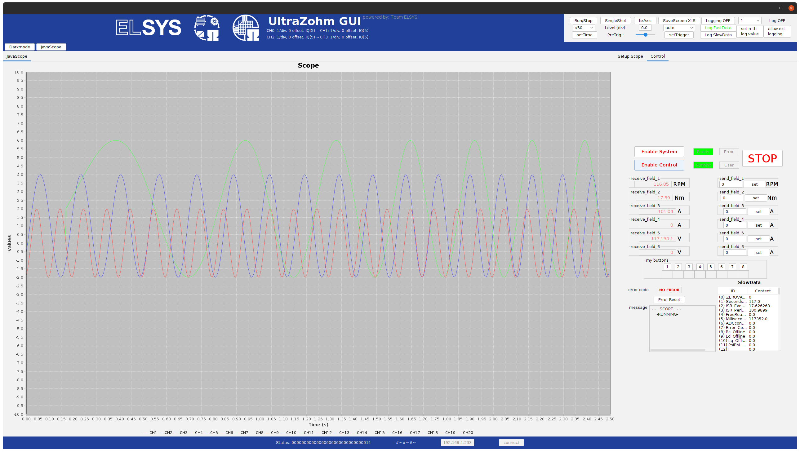
Fig. 5 Visible chirp signals#
This concludes the second tutorial.