Controlling a PMSM IP core with the CurrentControl module#
Aim of the tutorial#
In this tutorial the PMSM IP core will be added to the Vivado project and controlled using the CurrentControl.
Requirements#
The following tutorial requires:
Initial steps#
Open the project in
File -> Project -> OpenChoose the file
~/ultrazohm/ultrazohm_sw/vivado/project/ultrazohm.xprIn Vivado project open up the Block Design.
Extend the
uz_userblock.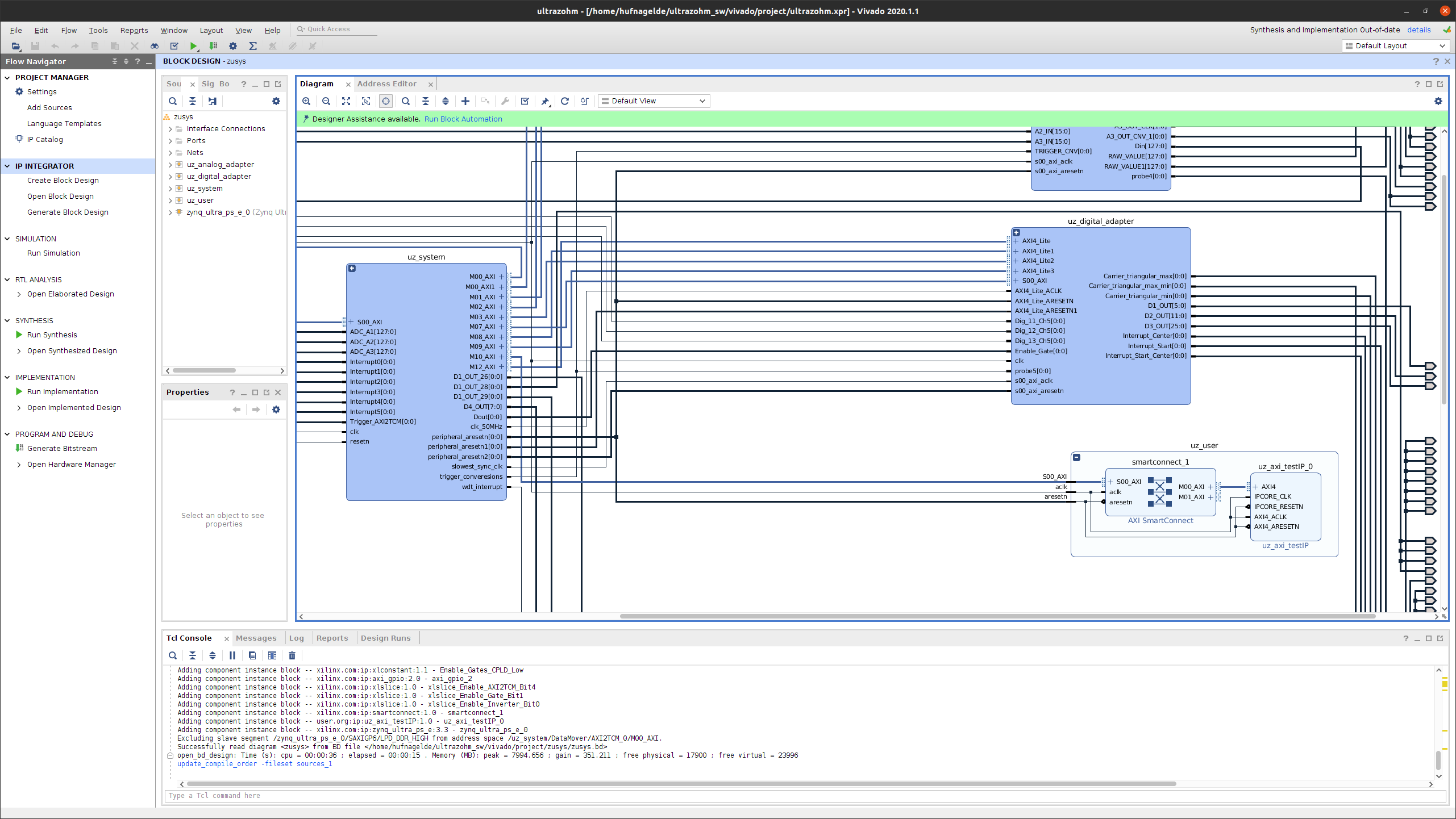
Fig. 13 Block design in Vivado.#
Right click on the
uz_userblock and selectAdd IP ...and search for theuz_pmsm_model.Double click on the result. The IP core should now reside inside the
uz_userblock.Double click on the
AXI smartconnectand increase the number of Master interfaces by one.Connect the IP core as shown below.
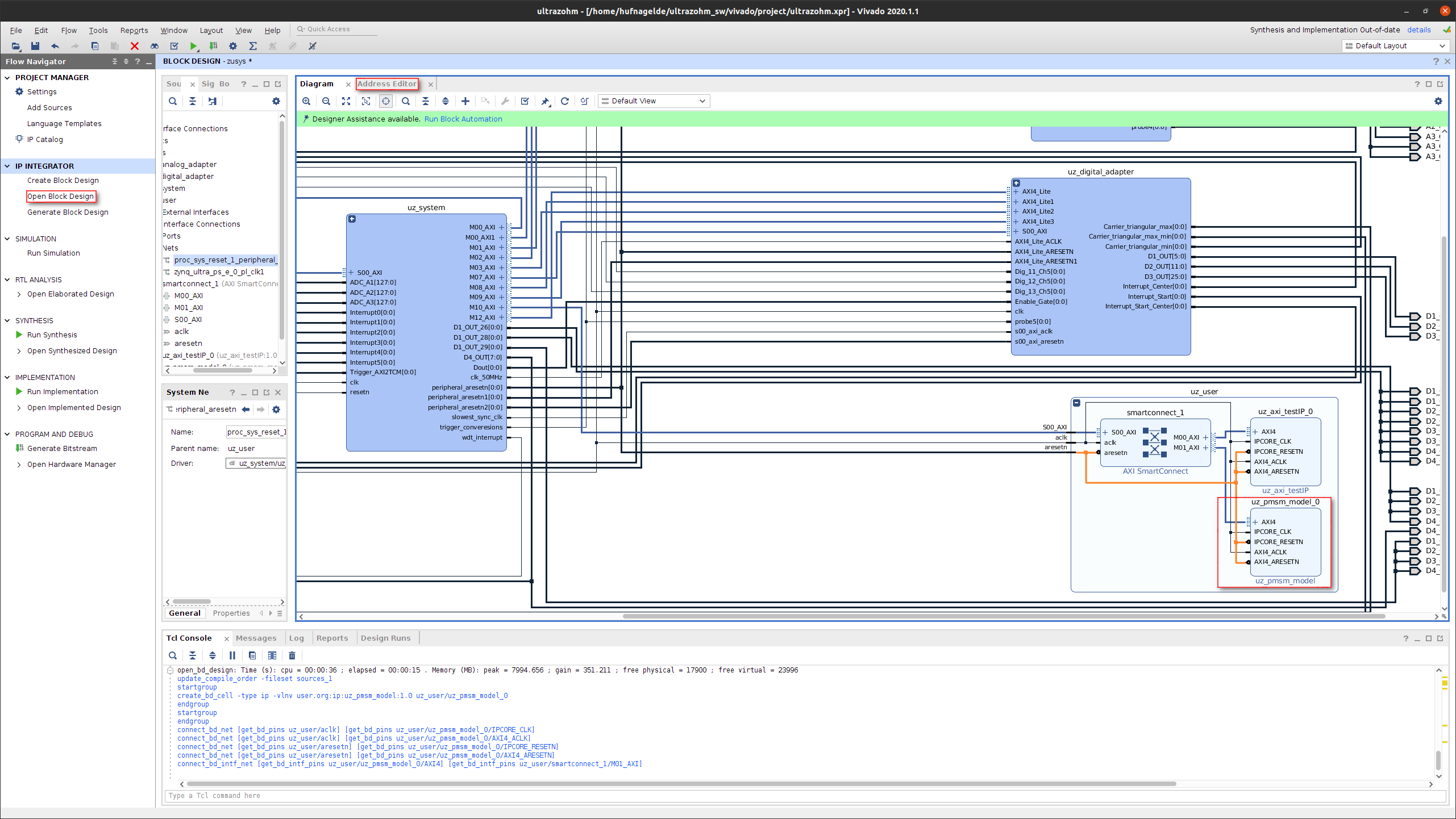
Fig. 14 Block design in Vivado.#
Click on the Address Editor tab and assign the new IP-Block an address by right clicking on the entry and selecting Assign.
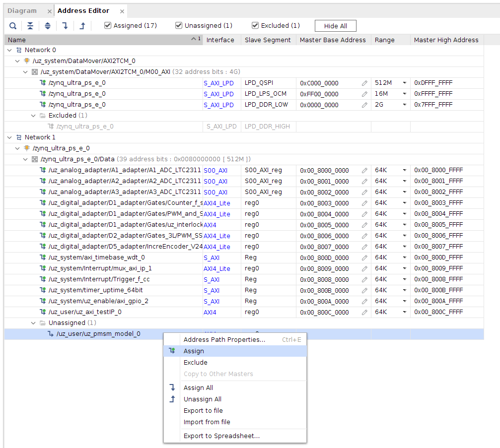
Fig. 15 Assign IP-address in Vivado.#
Note
If the new IP core shows up as unconnected instead of unassigned, delete the
AXI smartconnectin theuz_userblock and add it again with the same connections.Save the project, generate and export the bitstream as done in Generate the Bitstream with Vivado.
Generate the Vitis workspace as done in Generate the Vitis workspace.
Open the
uz_global_configuration.hfile and increase#define UZ_PMSMMODEL_MAX_INSTANCESby one. This way, one instance of the PMSM IP core driver can be used.At the same time check, that the
UZ_PWM_FREQUENCYis set to20.0e3f.In the
main.hadd the following includes.#include "IP_Cores/uz_pmsmMmodel/uz_pmsmModel.h"#include "xparameters.h"#include "uz/uz_CurrentControl/uz_CurrentControl.h"
In the
main.cadd another entry (e.g.init_pmsm) to theinit_chainenum andswitch-casestructure after theinit_softwarecase.Add the declaration as a global variable of the PMSM IP core before the
main-function.Add to the new
init_CurrentControl_pmsmcase the config struct and the init-function as show in the PMSM IP core docs.Note
The base-address needed is different to the one specified in the PMSM IP core docs. We implemented the IP core in the
uz_usersubblock in Vivado, therefore the IP core base address has to be adjusted to the following:XPAR_UZ_USER_UZ_PMSM_MODEL_0_BASEADDR. If the IP core is not included into the block design in a subblock, the base address form the PMSM IP core docs is the correct one.Initialize in the same switch-case the CurrentControl as shown here.
Your
main.cshould look similar to this now.1 //.... 2 enum init_chain 3 { 4 init_assertions = 0, 5 init_gpios, 6 init_software, 7 init_CurrentControl_pmsm, 8 init_ip_cores, 9 print_msg, 10 init_interrupts, 11 infinite_loop 12 }; 13 uz_pmsmModel_t *pmsm=NULL; 14 uz_CurrentControl_t* CurrentControl_instance = NULL; 15 //.... 16 int main(void) 17 { 18 int status = UZ_SUCCESS; 19 while (1) 20 { 21 switch (initialization_chain) 22 { 23 //.... 24 case init_software: 25 Initialize_Timer(); 26 uz_SystemTime_init(); 27 JavaScope_initalize(&Global_Data); 28 initialization_chain = init_CurrentControl_pmsm; 29 break; 30 case init_CurrentControl_pmsm:; 31 struct uz_PMSM_t config_PMSM = { 32 .Ld_Henry = 3.00e-04f, 33 .Lq_Henry = 3.00e-04f, 34 .Psi_PM_Vs = 0.0075f}; 35 struct uz_PI_Controller_config config_id = { 36 .Kp = 0.25f, 37 .Ki = 158.8f, 38 .samplingTime_sec = 0.00005f, 39 .upper_limit = 10.0f, 40 .lower_limit = -10.0f}; 41 struct uz_PI_Controller_config config_iq = { 42 .Kp = 0.25f, 43 .Ki = 158.8f, 44 .samplingTime_sec = 0.00005f, 45 .upper_limit = 10.0f, 46 .lower_limit = -10.0f}; 47 struct uz_CurrentControl_config config_CurrentControl = { 48 .decoupling_select = linear_decoupling, 49 .config_PMSM = config_PMSM, 50 .config_id = config_id, 51 .config_iq = config_iq, 52 .max_modulation_index = 1.0f / sqrtf(3.0f)}; 53 CurrentControl_instance = uz_CurrentControl_init(config_CurrentControl); 54 struct uz_pmsmModel_config_t pmsm_config={ 55 .base_address=XPAR_UZ_USER_UZ_PMSM_MODEL_0_BASEADDR, 56 .ip_core_frequency_Hz=100000000, 57 .simulate_mechanical_system = true, 58 .r_1 = 0.085f, 59 .L_d = 3.00e-04f, 60 .L_q = 3.00e-04f, 61 .psi_pm = 0.0075f, 62 .polepairs = 4.0f, 63 .inertia = 3.24e-05f, 64 .coulomb_friction_constant = 0.01f, 65 .friction_coefficient = 0.001f}; 66 pmsm=uz_pmsmModel_init(pmsm_config); 67 initialization_chain = init_ip_cores; 68 break; 69 case init_ip_cores: 70 //.... 71 } 72 } 73 return (status); 74 }
Add the code below to the
isr.c. This will write the input and outputs of the IP core. The CurrentControluz_CurrentControl_samplefunction will give out reference voltages for the PMSM IP core.1 //.... 2 extern uz_pmsmModel_t *pmsm; 3 extern uz_CurrentControl_t* CurrentControl_instance; 4 uz_3ph_dq_t reference_currents_Amp = {0}; 5 uz_3ph_dq_t measured_currents_Amp = {0}; 6 uz_3ph_dq_t CurrentControl_output_Volts = {0}; 7 float omega_el_rad_per_sec = 0.0f; 8 struct uz_pmsmModel_inputs_t pmsm_inputs={ 9 .omega_mech_1_s=0.0f, 10 .v_d_V=0.0f, 11 .v_q_V=0.0f, 12 .load_torque=0.0f 13 }; 14 struct uz_pmsmModel_outputs_t pmsm_outputs={ 15 .i_d_A=0.0f, 16 .i_q_A=0.0f, 17 .torque_Nm=0.0f, 18 .omega_mech_1_s=0.0f 19 }; 20 void ISR_Control(void *data) 21 { 22 //.... 23 if (current_state==control_state) 24 { 25 uz_pmsmModel_trigger_input_strobe(pmsm); 26 uz_pmsmModel_trigger_output_strobe(pmsm); 27 pmsm_outputs=uz_pmsmModel_get_outputs(pmsm); 28 measured_currents_Amp.d = pmsm_outputs.i_d_A; 29 measured_currents_Amp.q = pmsm_outputs.i_q_A; 30 omega_el_rad_per_sec = pmsm_outputs.omega_mech_1_s * 4.0f; 31 CurrentControl_output_Volts = uz_CurrentControl_sample(CurrentControl_instance, reference_currents_Amp, measured_currents_Amp, 24.0f, omega_el_rad_per_sec); 32 pmsm_inputs.v_q_V=CurrentControl_output_Volts.q; 33 pmsm_inputs.v_d_V=CurrentControl_output_Volts.d; 34 uz_pmsmModel_set_inputs(pmsm, pmsm_inputs); 35 } 36 //.... 37 }
In the
javascope.hreplace theJS_OberservableDataenum with the following.// Do not change the first (zero) and last (end) entries. enum JS_OberservableData { JSO_ZEROVALUE=0, JSO_i_q, JSO_i_d, JSO_omega, JSO_v_d, JSO_v_q, JSO_ENDMARKER };
Change the description of
send_field_1andsend_field_2toi_q_refandi_d_refrespectively.Adjust the labels of these send_fields to
A.Change the
receive_field_Xdescriptions to:RCV_FLD_ZEROVALUE=0, i_q, i_d, omega_m, v_q, v_d, receive_field_6, receive_field_7, receive_field_8, receive_field_9, receive_field_10, receive_field_11, receive_field_12, receive_field_13, receive_field_14, receive_field_15, receive_field_16, receive_field_17, receive_field_18, receive_field_19, receive_field_20, RCV_FLD_ENDMARKER
Change their label to:
 RCV_LABELS_ZEROVALUE=0,
 A,
 A,
 rad/s,
 V,
 V,
 sec,
 -,
 -,
 -,
 -,
 -,
 -,
 -,
 -,
 -,
 -,
 -,
 -,
 -,
 -,
 RCV_LABELS_ENDMARKER
Change the displayed values of the
receive_field_Xto the following. This is done to display the valuesSLOWDAT_DISPLAY_ZEROVALUE=0, JSSD_FLOAT_i_q, JSSD_FLOAT_i_d, JSSD_FLOAT_speed, JSSD_FLOAT_u_q, JSSD_FLOAT_u_d, JSSD_FLOAT_SecondsSinceSystemStart, JSSD_FLOAT_Error_Code, SLOWDAT_DISPLAY_ENDMARKER
In the javascope.c file add the pmsm input/outputs and replace the content of the
JavaScope_initalizefunction.1 //.... 2 extern struct uz_pmsmModel_outputs_t pmsm_outputs; 3 extern struct uz_pmsmModel_inputs_t pmsm_inputs; 4 5 int JavaScope_initalize(DS_Data* data) 6 { 7 //.... 8 // Store every observable signal into the Pointer-Array. 9 // With the JavaScope, signals can be displayed simultaneously 10 // Changing between the observable signals is possible at runtime in the JavaScope. 11 // the addresses in Global_Data do not change during runtime, this can be done in the init 12 js_ch_observable[JSO_i_q] = &pmsm_outputs.i_q_A; 13 js_ch_observable[JSO_i_d] = &pmsm_outputs.i_d_A; 14 js_ch_observable[JSO_omega] = &pmsm_outputs.omega_mech_1_s; 15 js_ch_observable[JSO_v_d] = &pmsm_inputs.v_d_V; 16 js_ch_observable[JSO_v_q] = &pmsm_inputs.v_q_V; 17 18 // Store slow / not-time-critical signals into the SlowData-Array. 19 // Will be transferred one after another 20 // The array may grow arbitrarily long, the refresh rate of the individual values decreases. 21 // Only float is allowed! 22 js_slowDataArray[JSSD_FLOAT_u_d] = &(pmsm_inputs.v_d_V); 23 js_slowDataArray[JSSD_FLOAT_u_q] = &(pmsm_inputs.v_q_V); 24 js_slowDataArray[JSSD_FLOAT_i_d] = &(pmsm_outputs.i_d_A); 25 js_slowDataArray[JSSD_FLOAT_i_q] = &(pmsm_outputs.i_q_A); 26 js_slowDataArray[JSSD_FLOAT_speed] = &(pmsm_outputs.omega_mech_1_s); 27 js_slowDataArray[JSSD_FLOAT_SecondsSinceSystemStart]= &(System_UpTime_seconds); 28 } 29 //....
In the
ipc_ARM.cfile add theextern uz_3ph_dq_t reference_currents_Ampstruct.Adjust the
Set_Send_Field_1andSet_Send_Field_2cases with the following code. This way we can transmit reference currents from the GUI to the R5.1 //.... 2 extern uz_3ph_dq_t reference_currents_Amp; 3 4 int ipc_Control_func(uint32_t msgId, float value, DS_Data *data) 5 { 6 //.... 7 case (Set_Send_Field_1): 8 reference_currents_Amp.q = value; 9 break; 10 11 case (Set_Send_Field_2): 12 reference_currents_Amp.d = value; 13 break; 14 //.... 15 }
Build the changes. If errors exist, fix them.
Flash the UltraZohm and connect the GUI.
Choose the appropriate channels in the Setup Scope and set a reference current for the q-axis, e.g. 3A.
Press Enable System and Enable Control and you should see, that the PMSM is running.
Notice, that the speed changes, if the current increases. This is the case, because the PMSM IP core is configured, to simulate the mechanical system.
Increasing the current over ~9.32A is not possible at first. This is the case, because the CurrentControl has a Space vector limitation to limit the voltage from exceeding the DC-link voltage.
Setting a negative d-current (e.g. -5A) lets you increase the q-current further. The machine operates now in the field weakening territory.
Try out different combinations of d- and q-currents and observe how the PMSM model reacts.
This concludes the fifth tutorial.