Modifying the GUI#
Aim of the tutorial#
In this tutorial, the three-phase wave from the wavegen library will be used. Configuration values of the three-phase wave will be modified during runtime via the GUI.
Requirements#
The following tutorial requires:
Guideline#
The GUI has eight general-purpose buttons in the Control panel, which can be mapped to our needs.

Fig. 6 General-purpose buttons in the Control panel of the GUI#
Discard any changes you made to the code basis in the previous tutorial.
Add the include statement
#include "uz/uz_Transformation/uz_Transformation.h"and#include "uz/uz_wavegen/uz_wavegen.h"to themain.hfile.This
uz_Transformation.hheader file includes structs for common coordinate systems used in the motor control world (e.g., abc-, dq0-system, etc.).For further information see Coordinate Transformation.
Add a new global
boolvariable to theisr.cfile which will be used to enable the three-phase wave.Add a new global
uz_3ph_abc_tstruct to the same file. This will store the calculated values of theuz_wavegen_three_phase_samplefunction.Add three new global
floatvariables titled, amplitude, frequency and offset and initialize them with values.Add an if statement with the new bool variable inside the
if (current_state==control_state)statement.Add the
uz_wavegen_three_phase_samplefunction inside your new if statement.1 //.... 2 // Global variable structure 3 extern DS_Data Global_Data; 4 5 uz_3ph_abc_t three_phase_output = {0}; 6 bool is_three_phase_active = false; 7 float amplitude = 2.0f; 8 float frequency = 5.0f; 9 float offset = 0.0f; 10 11 12 //============================================================================================================================================================== 13 //---------------------------------------------------- 14 // INTERRUPT HANDLER FUNCTIONS 15 // - triggered from PL 16 // - start of the control period 17 //---------------------------------------------------- 18 static void ReadAllADC(); 19 20 void ISR_Control(void *data) 21 { 22 uz_SystemTime_ISR_Tic(); // Reads out the global timer, has to be the first function in the isr 23 ReadAllADC(); 24 update_speed_and_position_of_encoder_on_D5(&Global_Data); 25 26 platform_state_t current_state=ultrazohm_state_machine_get_state(); 27 if (current_state==control_state) 28 { 29 if (is_three_phase_active) { three_phase_output = uz_wavegen_three_phase_sample(amplitude, frequency, offset); } 30 } 31 uz_PWM_SS_2L_set_duty_cycle(Global_Data.objects.pwm_d1, Global_Data.rasv.halfBridge1DutyCycle, Global_Data.rasv.halfBridge2DutyCycle, Global_Data.rasv.halfBridge3DutyCycle); 32 // Set duty cycles for three-level modulator 33 PWM_3L_SetDutyCycle(Global_Data.rasv.halfBridge1DutyCycle, 34 Global_Data.rasv.halfBridge2DutyCycle, 35 Global_Data.rasv.halfBridge3DutyCycle); 36 JavaScope_update(&Global_Data); 37 // Read the timer value at the very end of the ISR to minimize measurement error 38 // This has to be the last function executed in the ISR! 39 uz_SystemTime_ISR_Toc(); 40 } 41 //....
In the
javascope.cfile, add thethree_phase_outputstruct with theexternkeyword.Replace the assignment of the addresses for the
JSO_ua,JSO_ubandJSO_ucmembers of thejs_ch_observablearray with the three elements of thethree_phase_outputstruct.1 //.... 2 extern uz_3ph_abc_t three_phase_output; 3 4 int JavaScope_initalize(DS_Data* data) 5 { 6 //.... 7 js_ch_observable[JSO_ua] = &three_phase_output.a; 8 js_ch_observable[JSO_ub] = &three_phase_output.b; 9 js_ch_observable[JSO_uc] = &three_phase_output.c; 10 //.... 11 } 12 //....
Open the
ipc_ARM.cfile and add theis_three_phase_activevariable with theexternkeyword.This file processes the commands send from the GUI.
This includes, e.g., the commands for the Enable System and Enable Control buttons, the eight My_Buttons and the send_fields.
Scroll down to the cases of the
My_Buttonsin the switch-case structure and assign the variableis_three_phase_activethe value true in thecase (My_Button_4):.This sets the value of the bool variable to true, if the
My_Button_4is pressed.Keep in mind that the corresponding button in the GUI is not a toggle button. Pressing this button will always set the variable to true. It will not change the value depending on if the button is selected (pressed) or unselected.
To be able to disable the three-phase wave again, assign in the case
case (My_Button_5):the variableis_three_phase_activethe value false.Set the
ultrazohm_state_machine_set_userLED()to true, ifMy_Button_4is pressed and to false, ifMy_Button_5is pressed. This will turn the userLED on, when the three-phase wave is active.Comment in the code of
Bit_7andBit_8forMy_Button_4andMy_Button_5and change it to the following.These status bits relay information from the R5 back to the GUI.
They are, e.g., used to sync the Ready LED, Running LED etc.
For this specific tutorial, these two bits are used to relay the information to the GUI that the button press was acknowledged by the R5.
 1 //....
 2 extern bool is_three_phase_active;
 3
 4 int ipc_Control_func(uint32_t msgId, float value, DS_Data *data)
 5 {
 6    //....
 7    case (My_Button_4):
 8       is_three_phase_active = true;
 9       ultrazohm_state_machine_set_userLED(true);
10       break;
11
12    case (My_Button_5):
13       is_three_phase_active = false;
14       ultrazohm_state_machine_set_userLED(false);
15       break;
16    //....
17    /* Bit 7 - My_Button_4 */
18    if (is_three_phase_active) {
19       js_status_BareToRTOS |= 1 << 7;
20    } else {
21       js_status_BareToRTOS &= ~(1 << 7);
22    }
23
24    /* Bit 8 - My_Button_5 */
25    if (!is_three_phase_active) {
26       js_status_BareToRTOS |= 1 << 8;
27    } else {
28       js_status_BareToRTOS &= ~(1 << 8);
29         }
30    //....
31 }
Build the changes and flash the UltraZohm.
Open the uz_GUI and select the ua, ub and uc members in the channel selection and hide
CH4andCH5.Change the UltraZohm to the Control state by pressing the respective buttons.
Because of the additional if statement in the
isr.cfile, no three-phase wave should be visible in the scope.Press the
My_Button_4. The userLED should turn on and the three-phase wave should be visible in the scope and the field below theMy_Button_4should turn green.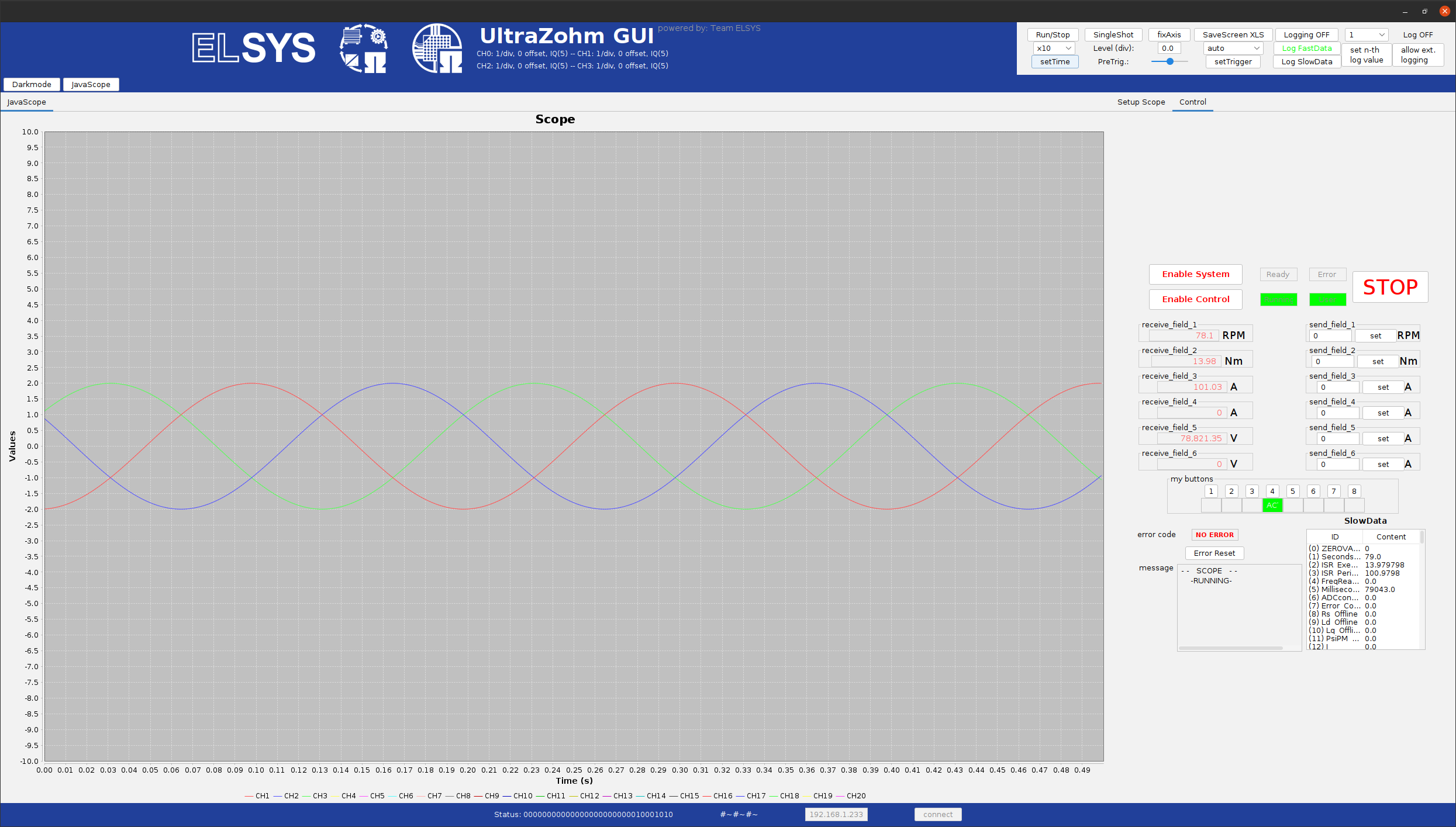
Fig. 7 Visible three-phase wave#
Disable and enable the three-phase wave with the respective buttons to see that everything is working as intended. If it is successful, close the GUI.
It is possible to send values from the GUI to the R5 via the send_fields. These will be used to modify the three-phase wave during runtime.
Six values are available that can be used as references or setpoints for the user application.
For further information, refer to JavaScope.
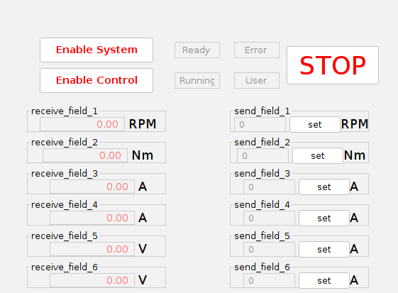
Fig. 8 General-purpose Send_fields#
In the
javascope.hfile, we will modify the send_fields labels to our needs.Change the description for the send_fields from
send_field_1tosend_field_3toamplitude,offsetandfrequency.You can adjust the labels next to the send_fields. Change them for the first three send_fields to, e.g., V.
These descriptions and labels are purely cosmetic.
They do not change anything in the code basis. They are therefore commented out as well.
Go to the
ipc_ARM.cfile and add the three variablesamplitude,frequencyandoffsetfrom theisr.cwith the extern keyword.In the cases
Set_Send_Field_1toSet_Send_Field_3, give the corresponding variable the valuevalue.I.e., description says for
send_field_1nowamplitude,amplitudehas to be assigned in theSet_Send_Field_1case.Do not change the name of the case itself.
With these changes, the value in the text box of the Send_fields will be given to the specified variable from the R5.
The final version of the ipc_ARM.c file should look similar to this.
 1 //....
 2 extern bool is_three_phase_active;
 3 extern float amplitude;
 4 extern float frequency;
 5 extern float offset;
 6
 7 int ipc_Control_func(uint32_t msgId, float value, DS_Data *data)
 8 {
 9    //....
10    case (My_Button_4):
11       is_three_phase_active = true;
12       ultrazohm_state_machine_set_userLED(true);
13       break;
14
15    case (My_Button_5):
16       is_three_phase_active = false;
17       ultrazohm_state_machine_set_userLED(false);
18       break;
19    //....
20    case (Set_Send_Field_1):
21       amplitude = value;
22       break;
23
24    case (Set_Send_Field_2):
25       frequency = value;
26       break;
27
28    case (Set_Send_Field_3):
29       offset = value;
30       break;
31    //....
32    /* Bit 7 - My_Button_4 */
33    if (is_three_phase_active) {
34       js_status_BareToRTOS |= 1 << 7;
35    } else {
36       js_status_BareToRTOS &= ~(1 << 7);
37    }
38
39    /* Bit 8 - My_Button_5 */
40    if (!is_three_phase_active) {
41       js_status_BareToRTOS |= 1 << 8;
42    } else {
43       js_status_BareToRTOS &= ~(1 << 8);
44         }
45    //....
46 }
Build the changes and flash the UltraZohm.
Start up the GUI, select the ua, ub and uc members in the channel selection and activate the three-phase wave.
Try different values for the amplitude, offset and frequency and see how the changes reflect in the scope.
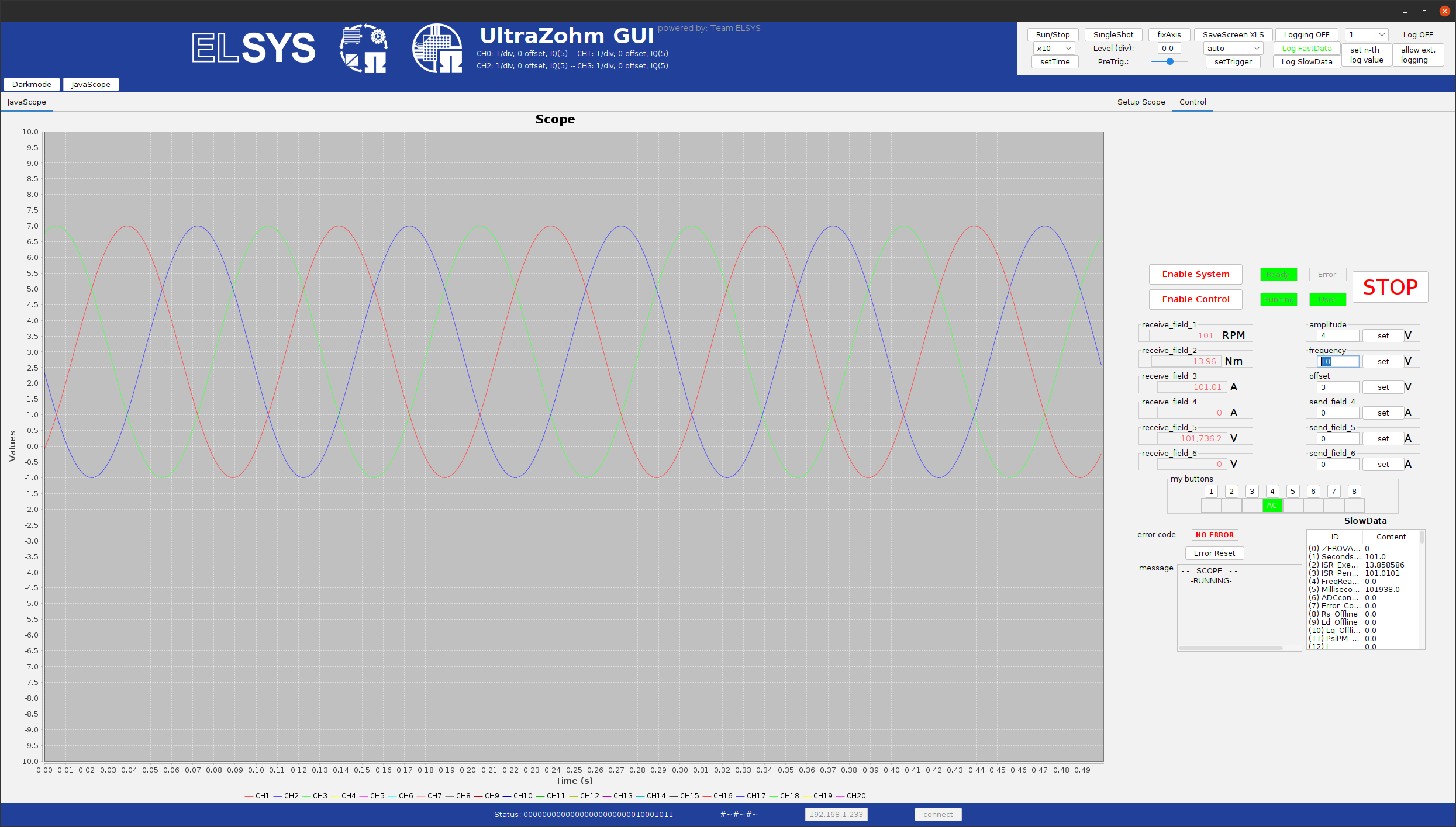
Fig. 9 Visible three-phase wave with different config settings and the changes made to the GUI#
This concludes the third tutorial.