Virtual Input Output (VIO)#
Aim of the tutorial#
In this tutorial, the Virtual Input Output (VIO) IP core is used to light up LEDs on the optical adapter board.
After this tutorial, you can:
Connect to the programmed FPGA with Vivado
Use the VIO
Test the optical adapter board
Requirements#
The following tutorial requires:
Complete UltraZohm Toolchain (Vivado, Vitis, ultrazohm_sw repository)
UltraZohm connected to your PC by Ethernet and USB (JTAG)
Optical adapter card in slot D3 (Digital Optical)
UltraZohm Setup#
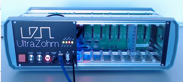
The UltraZohm has to be connected to a PC by Ethernet and USB (JTAG-Programmer) and the optical adapter card is in D3.
VIO usage#

Updated information#
With optical adapter card 2v02 one must set Output 19 to high, since this is the ENABLE signal of the optical card.
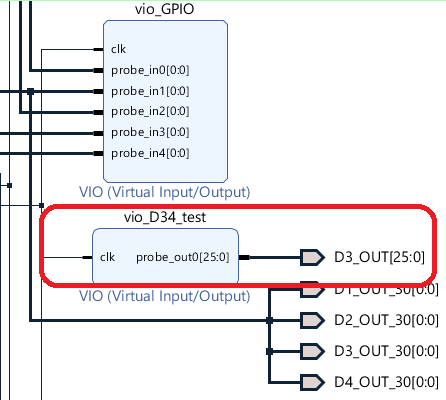
VIO IP core at 1:02 has a different name now. Furthermore, the output ports are labeled D3_OUT[25:0] instead of Dig_Ch4[25:0].
Furthermore, the selection for the hw_vio channel at 1:25 changed as well. It is now hw_vio_6 instead of hw_vio_5.