Interlock and Deadtime module (2L)#
The interlock and dead time IP core prevents the TOP and BOT gate signal being high at the same time and introduces a variable dead time between high states.
The dead time has a range of \(0\,\mu s\) to \(10.23\,\mu s\) with \(10\,ns\) resolution if the IP core is driven by a \(100\,MHz\) clock.
If the requested dead time is not an integer multiple of the inverse IP core clock frequency (e.g., \(10\,ns\)) the driver rounds up using ceil.
Warning
It is possible to set the dead time to \(0\,\mu s\)! Check if your power electronics can handle this!
The module features three legs, i.e., is intended for two level voltage inverters. IP core is generated using Simulink HDL-Coder version 2021a.
Software Driver#
The software driver for the module is located at ultrazohm_sw/vitis/export/Baremetal/IP_Cores/uz_interlockDeadtime2L.
The driver interface is located in uz_interlockDeadtime2L.h and has four public methods:
uz_interlockDeadtime2L_set_enable_output
uz_interlockDeadtime2L_get_enable_output
uz_interlockDeadtime2L_set_deadtime_us
uz_interlockDeadtime2L_get_deadtime_us
Additionally, the static allocator has to be used for initialization and allocation of instances of the struct.
How-to use#
An example initialization and usage is listed in the following.
1#include "IP_Cores/uz_interlockDeadtime2L/uz_interlockDeadtime2L_staticAllocator.h"
2int main(void){
3uz_interlockDeadtime2L_handle deadtime_slotd1 = uz_interlockDeadtime2L_staticAllocator_slotD1();
4uz_interlockDeadtime2L_set_enable_output(deadtime_slotd1, true);
5}
In configure the configuration values in the static allocator function using the base address from xparameters.h.
uz_interlockDeadtime2L_staticAllocator_slotD1#1static uz_interlockDeadtime2L interlock_slotD1 = {
2 .base_address = XPAR_GATES_UZ_INTERLOCKDEADTIME_0_BASEADDR,
3 .clock_frequency_MHz = 100,
4 .deadtime_us = 1,
5 .inverse_bottom_switch = false
6};
To change the dead time of the module at runtime disable the output and set the dead time:
1uz_interlockDeadtime2L_set_enable_output(deadtime_slotd1,false);
2uz_interlockDeadtime2L_set_deadtime_us(deadtime_slotd1,1.0f);
3uz_interlockDeadtime2L_set_enable_output(deadtime_slotd1,true);
It is not possible to change other values of the module after initialization.
IP Core Hardware#
Fig. 352 Top view of the Module.#
Fig. 352 shows the module.
The module takes the gate signals of a three phase inverter S0..S5 as input and outputs them as S0_out..S5_out.
The output is enabled if AXI_EnableOutput is true.
The enable signal is routed to enableFB to be used by other IP cores in the PL.
The Interlock prevents TOP and BOT (S0 & S1, S2 & S3, S4 & S5) of each signal to be true at the same time.
The Deadtime adds a variable length delay to each rising edge of the input signal.
The number of IP core clock cycles added is determined by AXI_DelayCycles.
It is possible to inverse the signal of the bottom switch by setting AXI_InverseBotSwitch to true, see Inverse Bottom switch.
New values for IP core are written by the Software Driver.
Interface#
Port Name |
Port Type |
Data Type |
Target Platform Interfaces |
|---|---|---|---|
S0 |
Inport (TOP) |
boolean |
External Port |
S1 |
Inport (BOT) |
boolean |
External Port |
S2 |
Inport (TOP) |
boolean |
External Port |
S3 |
Inport (BOT) |
boolean |
External Port |
S4 |
Inport (TOP) |
boolean |
External Port |
S5 |
Inport (BOT) |
boolean |
External Port |
s0_out |
Outport |
boolean |
External Port |
s1_out |
Outport |
boolean |
External Port |
s2_out |
Outport |
boolean |
External Port |
s3_out |
Outport |
boolean |
External Port |
s4_out |
Outport |
boolean |
External Port |
s5_out |
Outport |
boolean |
External Port |
enableFB |
Outport |
boolean |
External Port |
axi_fb_InverseBotSwitch |
Outport |
boolean |
0x100 |
axi_fb_DelayCycles |
Outport |
fi(0;10;0) |
0x104 |
axi_fb_enable |
Outport |
boolean |
0x108 |
axi_InverseBotSwitch |
Inport |
boolean |
0x10C |
axi_EnableOutput |
Inport |
boolean |
0x110 |
axi_DelayCycles |
Inport |
fi(0;0;0) |
0x114 |
Inverse Bottom switch#
Fig. 353 Inverses the signal of the BOT switches (S1, S3, S5), if AXI_fb_InverseBotSwitch is true.#
Interlock#
Fig. 354 Interlock prevents the TOP/BOT to switch to true if BOT/TOP is already true.#
Deadtime#
Fig. 355 Deadtime module#
The deadtime module adds a delay to every rising edge on the signals S0..S5.
If TOP_IN/BOT_IN is true the 10 bit counter starts counting until the value of DelayCycles is reached.
The switch changes to pass through input one, which in turn makes the AND switch to true.
The true signal is held by the resettable delay block.
As soon as TOP_IN/BOT_In switches to false the AND switches to false.
The counter for the delay is reset after TOP_IN/BOT_IN switches from true to false.
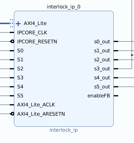
Vivado Example#

Fig. 356 Screenshot of IP core in Vivado.#
The clock frequency for IPCORE_CLK and AXI4_Lite_ACLK is 100 MHz.
Port Name |
CLK |
Usage |
|---|---|---|
AXI4_Lite |
100 MHz |
Connecto to AXI_smartconnect |
IPCORE_CLK |
100 MHz |
Connect to 100 MHz clock |
IPCORE_RESETN |
100 MHz |
Connect to 100 MHz reset |
AXI4_LiteACLK |
100 MHz |
Connecto to IPCORE_CLK |
AXI4_Lite_ARESETN |
100 MHz |
Connect to IPCORE_RESETN |