Incremental Encoder#
The incremental encoder IP core (IncreEncoder_V26) evaluates signals of an incremental encoder and is compatible to Digital Encoder 1v00.
It features multiple possibilities to calculate the rotor position and the rotational speed of the encoder.
- Position
Calculates the rotational position of the encoder based on counting rising and falling edges on the A and B-lane of the encoder. Resets to zero based on the I-lane (once per mechanical revolution).
- Position (electrical)
Calculates the rotational position of the encoder and transforms the position to the electrical position of electric drive (e.g., permanent magnet synchronous machines). Uses the number of pole pairs to divide one mechanical turn of the encoder to (multiple) turns of the electrical system. Can only be used if the number of increments is an integer multiple of the number of pole pairs! The value of
drive_pole_pairin the driver configuration has to be an integer multiple of the increments per turn or set to zero. Ifdrive_pole_pairis an integer multiple of increments per turn, the electrical angle can be used and read by callinguz_incrementalEncoder_get_theta_el. Ifdrive_pole_pairis set to0, the function can not be called (assertion fires if it is called). Ifdrive_pole_pairis not0and not an integer multiple of increments per turn, the initialization of the driver fails with an assertion. Note that the FPGA output port of the IP core outputs the (potentially false!) electrical position regardless of this setting!- Rotational speed
Calculates the rotational speed of the drive by counting the time between two consecutive rising edges of the A-lane in combination with an speed-dependent oversampling mechanism and subsequent filtering of the speed signal in the IP core. The oversampling mechanism allows to skip edges to improve the measurement at higher speeds.
- Direction of rotation
Determines the direction of the rotation (clockwise / counterclockwise)
Hardware filter of rotational speed#
Subsystem omega_by_measure_time outputs \(\omega_{raw}\), new_measurement and oversampling factor \(k_{Oversample}\).
The following calculation is done:
This is fed to the Average_linear_Reg with the constants \(S_{factor}=6\) and \(S_{invFactor} = \frac{1}{6}\) (not used at all).
Whenever new_measurement is true, the current value of \(\omega_{scaled}\) is added to an internal storage that sums up the rotational speed.
After six (\(S_{factor}=6\)) measurements the internal storage is reset to zero, restarting the averaging.
The value of the internal storage is divided by the number of samples that are currently in the internal storage and output.
IP Core Hardware#
The IP core is generated using Matlab/Simulink HDL-Coder based on the model inc_enc_v26.slx (in ultrazohm_sw/ip-cores/IncreEncoder_V26_ip/Simulation/).
Vivado integration#
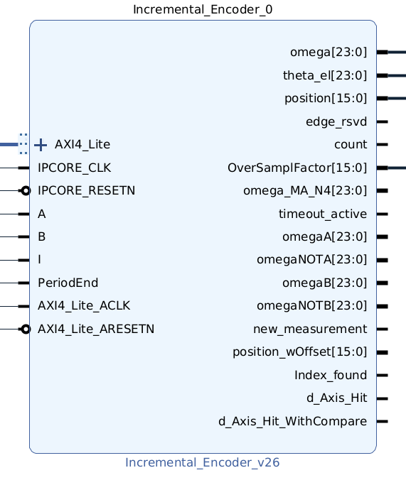
Fig. 414 Vivado block design of incremental encoder IP core.#
Warning
The IP core (IPCORE_CLK) has to be sourced by a clock with \(100 MHz\)! For lower frequencies the accuracy of the encoder result is not tested.
Configuration registers (AXI)#
The following configuration registers are available for the IP core. The software driver writes to the registers based on the configuration that is provided to the initialization function.
- PI2_Inc_AXI
Scales the output theta_el to \(0..2\pi\). Is calculated in the processor and written to the IP core. Calculation: \(\frac{2 \cdot \pi}{IncPerTurn \cdot QudratureFactor} \cdot PolePair\) with
PolePairbeing the pole pairs of the drive.- Timer_FPGA_ms
Scales the timer, that is used to calculate the rotational speed, from FPGA clock ticks to seconds w.r.t. the number of increments and \(2\pi\). Default is \(\frac{IncPerTurn}{f_{IP-Core}} \cdot \frac{1}{2\pi}=7.958e-06\) with \(f_{IP-Core}=100 MHz\) and \(IncPerTurn=5000\).
- IncPerTurn_mech
Configures the number of lines per mechanical revolution.
- IncPerTurn_elec
Configures the number of lines per electrical revolution, i.e., w.r.t. to the pole pairs of a electrical machine. Set to
IncPerTurn_mechdivided by pole pairs of the electrical machine.- OverSamplingFactor
Calculation of the rotational speed omega is based on measuring the time between rising edges of the A-lane. If
OverSampleFactor=1, every rising edge is used. ForOverSampleFactor=n, every n-th rising edge is used. Based on the setting, the IP core adapts the OverSampleFactor over the operating range of the drive. TheOverSamplingFactoris set byOmegaPerOverSampl_AXI4inrad/s. Default value is \(500 \frac{1}{min} \cdot \frac{2\pi}{60 s}=52.3599 s^{-1}\).- PeriodEnd
Used to reset the counter that is used to calculate the rotational speed, which is output at
countPerPeriod_AXI. Not recommended, use calculation based on time measurement based on counting edges of the A-lane instead (omega_AXI).- TimeoutValue
Used to set the timeout value in milliseconds for the
omega_outport. If a timeout occurs, theomega_outport will be set to zero after the configured value has passed.- PositionOffset
Sets the mechanical offset for the \(\theta_{mech}\). \(\theta_{mech}\) can only be used in the PL.
- ElectricalOffset
Sets the electrical offset for the \(\theta_{el}\). This changes the \(\theta_{el}\) in software and the PL.
- CountingDirection
Sets the counting direction of the angle and rotation. Can be configured via an enum. Default is clock_wise.
Table Interfaces of the incremental encoder IP core lists all input and output ports (AXI and external port) that are present in the IP core.
Port Name |
Port Type |
Data Type |
Target Platform Interfaces |
Function |
|---|---|---|---|---|
A |
Input |
bool |
External Signal |
Lane A of encoder |
B |
Input |
bool |
External Signal |
Lane B of encoder |
I |
Input |
bool |
External Signal |
Lane I of encoder (zero) |
PeriodEnd |
Input |
bool |
External Signal |
Resets subsystem that calculates |
Theta_el |
Output |
sfix24_En20 |
External Signal |
Theta electric based on the subsystem |
omega |
Output |
sfix24_En11 |
External Signal |
Rotational speed based on time measurement between rising edge of A-lane (subsystem |
position |
Output |
uint16_t |
External Signal |
Outputs the position of the encoder with a range of 0 to increments |
count |
Output |
bool |
External Signal |
1 if edge counter is triggered - 0 otherwise |
edge_rsvd |
Output |
bool |
External Signal |
1 if an edge is detected - 0 otherwise |
OverSamplFactor |
Output |
uint16_t |
External Signal |
Reads back the over sample factor of the speed calculation |
omega_MA_N4 |
Output |
sfix24_En11 |
External Signal |
omega but with an moving average over the last 4 measurements |
timeout_active |
Output |
bool |
External Signal |
Active if a timeout occurred |
omegaA |
Output |
sfix24_En11 |
External Signal |
omega calculated using only positive edges of the A Line |
omegaB |
Output |
sfix24_En11 |
External Signal |
omega calculated using only positive edges of the B Line |
omegaNOTA |
Output |
sfix24_En11 |
External Signal |
omega calculated using only negative edges of the A Line |
omegaNOTB |
Output |
sfix24_En11 |
External Signal |
omega calculated using only negative edges of the B Line |
new_measurement |
Output |
bool |
External Signal |
indicates that an omega measurement of a Line has been completed |
position_wOffset |
Output |
uint16_t |
External Signal |
Outputs the position shifted by |
Index_found |
Output |
bool |
External Signal |
Indicates whether the I-lane of the encoder has been found |
Reset |
Input |
bool |
AXI |
Resets the IP core |
Enable |
Input |
bool |
AXI |
Enables the IP core |
Timestamp |
Output |
uint32_t |
AXI |
Returns unique IP timestamp |
omega_AXI4 |
Output |
sfix24_En11 |
AXI |
same signal as omega |
omega_MA_N4_AXI4 |
Output |
sfix24_En11 |
AXI |
omega but with an moving average over the last 4 measurements |
theta_el_AXI4 |
Output |
sfix24_en20 |
AXI |
same signal as Theta_el |
position_AXI4 |
Output |
uint16_t |
AXI |
Outputs the position of the encoder with a range of 0 to increments |
direction_AXI4 |
Output |
sfix4 |
AXI |
1 if rotation is clockwise - 0 otherwise |
counterPerPeriod_AXI4 |
Output |
int16 |
AXI |
Result of |
PI2_Inc_AXI |
Input |
ufix24_En24 |
AXI |
Scales the output of |
Timer_FPGA_ms_AXI4 |
Input |
ufix32_En32 |
AXI |
Scales clock ticks to rad/s |
IncPerTurn_mech_AXI4 |
Input |
uint16_t |
AXI |
Number of increments of the encoder of one mechanical turn |
IncPerTurn_elek_AXI4 |
Input |
uint16_t |
AXI |
Number of increments of the encoder divided by pole pairs for electrical angle |
OmegaPerOverSampl_AXI4 |
Input |
sfix24_En11 |
AXI |
Oversampling factor for speed measurement - provided as multiple |
Position_offset_AXI4 |
Input |
uint16_t |
AXI |
Offset for theta_mech in increments |
Theta_el_offset_AXI4 |
Input |
uint16_t |
AXI |
Offset for theta_el in increments |
Timeout_value_AXI4 |
Input |
uint16_t |
AXI |
If a timeout occurs the omega_AXI4 port will be set to 0 after the specified time |
CW_CCW_Switch_AXI4 |
Input |
bool |
AXI |
Sets a clock_wise or counter_clock_wise counting direction |
Position_wOffset_AXI4 |
Output |
uint16_t |
AXI |
Outputs the position shifted by |
Index_found_AXI4 |
Output |
bool |
AXI |
Indicates whether the I-lane of the encoder has been found |
Software driver#
The software driver for the IP core handles the configuration of the aforementioned registers.
struct uz_incrementalEncoder_config encoder_D5_config={
              .base_address=XPAR_UZ_DIGITAL_ADAPTER_D5_ADAPTER_INCREMENTAL_ENCODER_0_BASEADDR,
              .ip_core_frequency_Hz=100000000U,
              .line_number_per_turn_mech=5000U,
              .OmegaPerOverSample_in_rpm=500.0f,
              .drive_pole_pair=4U,
              .Encoder_elec_Offset = 0U,
              .counting_direction = clock_wise,
              .Speed_Timeout_ms = 10U //10ms
};
uz_incrementalEncoder_t* test_instance=uz_incrementalEncoder_init(testconfig);
float omega=uz_incrementalEncoder_get_omega_mech(test_instance);
float theta_el=uz_incrementalEncoder_get_theta_el(test_instance);
uint32_t position=uz_incrementalEncoder_get_position(test_instance);
Driver reference#
-
typedef struct uz_incrementalEncoder_t uz_incrementalEncoder_t#
Object data type definition of the incremental encoder IP-Core driver.
-
enum uz_incrementalEncoder_counting_direction#
enum for readable configuring counting direction of the IP Core.
Values:
-
enumerator uz_incrementalEncoder_counting_clock_wise#
-
enumerator uz_incrementalEncoder_counting_counter_clock_wise#
-
enumerator uz_incrementalEncoder_counting_clock_wise#
-
struct uz_incrementalEncoder_config#
Configuration struct for the encoder driver.
Public Members
-
uint32_t base_address#
Base address of IP-Core instance
-
uint32_t ip_core_frequency_Hz#
Clock frequency of IP-Core
-
uint32_t line_number_per_turn_mech#
Number of lines eper one mechanical turn of the attached encoder
-
float OmegaPerOverSample_in_rpm#
Rotational speed omega in 1/min after which the OverSamplingFactor is increased by one
-
uint32_t drive_pole_pair#
Number of pole pairs of the electric drive that is attached to the encoder. Set to zero if no drive is attached or increments per mechanical turn is not an integer multiple of pole pairs
-
uint32_t Encoder_mech_Offset#
Set the Mechanical Encoder Offset in increments
-
uint32_t Encoder_elec_Offset#
Set the electrical Encoder Offset in increments
-
enum uz_incrementalEncoder_counting_direction counting_direction#
Set the counting direction to
0=clock_wise or
1=counter_clock_wise
-
uint32_t Speed_Timeout_ms#
Milliseconds after the omega_out jumps to zero if a timeout occurs
-
uint32_t base_address#
-
uz_incrementalEncoder_t *uz_incrementalEncoder_init(struct uz_incrementalEncoder_config config)#
Initialization of one instance of the driver for the incremental encoder IP-Core.
- Parameters:
config – Configuration values for the IP-Core
- Returns:
uz_incrementalEncoder_t* Pointer to initialized instance
-
float uz_incrementalEncoder_get_omega_mech(uz_incrementalEncoder_t *self)#
Returns the measured omega based on counting edges of the A-lane in 1/s.
- Parameters:
self – Pointer to the instance
- Returns:
float omega_mech
-
float uz_incrementalEncoder_get_theta_el(uz_incrementalEncoder_t *self)#
Returns the measured electrical angle in 0..2pi range if drive_pole_pair is not zero in the config.
- Parameters:
self – Pointer to the instance
- Returns:
float theta_el
-
uint32_t uz_incrementalEncoder_get_position(uz_incrementalEncoder_t *self)#
Returns the measured mechanical angle in 0..increments.
- Parameters:
self – Pointer to the instance
- Returns:
uint32_t position