Mux Axi / ISR Trigger Control#
Selects the PWM counter event that triggers ADC and the interrupt of the R5 processor
Selects ADC/ISR trigger ratio: trigger the ISR in the R5 every n-th ADC trigger event
(n = 1,2,3,...)
PWM counter events#
The
PWM and SS Controlas well as the 3-level PWM IP core use an up-down counterAt counter min and max those IP cores provide rising edge signals that are fed to the uz_mux_axi IP core
Those trigger signals depend on the selected PWM frequency
Interrupt sources#
The user selects the trigger source for ADC triggering via the
#defineINTERRUPT_ISR_SOURCE_USER_CHOICEinuz_global_configuration.h(see Global configuration)The selected trigger source also triggers the ISR in the R5 processor (see also Interrupts R5)
Below, as well as in
uz_global_configuration.h, the user will find the valid interrupt source options:
/** ISR trigger source
 *
 * chose here which of the above interrupt trigger you want to use:
 * 0 for Interrupt_2L_max_min
 * 1 for Interrupt_2L_min
 * 2 for Interrupt_2L_max
 * 3 for Interrupt_3L_start_center
 * 4 for Interrupt_3L_start
 * 5 for Interrupt_3L_center
 * 6 for Interrupt_timer_fcc
*/
ADC/ISR trigger ratio#
If necessary, the user can choose an integer multiple ratio between ADC and ISR triggering
This is done by setting the
INTERRUPT_ADC_TO_ISR_RATIO_USER_CHOICE#defineinuz_global_configuration.h
Example#
The user wants to have a PWM frequency of 100 kHz and an ISR frequency of 20 kHz:
The user selects the PWM frequency of 100 kHz: the define
UZ_PWM_FREQUENCYis set to100.0e3finuz_global_configuration.hThe trigger source is
Interrupt_2L_min: the defineINTERRUPT_ISR_SOURCE_USER_CHOICEis set to1Uinuz_global_configuration.hThe trigger ratio is set to 5 (100 kHz/20 kHz = 5): the define
INTERRUPT_ADC_TO_ISR_RATIO_USER_CHOICEis set to5Uinuz_global_configuration.h
#define INTERRUPT_ISR_SOURCE_USER_CHOICE        1U
#define INTERRUPT_ADC_TO_ISR_RATIO_USER_CHOICE  5U

#define UZ_D5_INCREMENTAL_ENCODER_RESOLUTION    5000.0f
#define UZ_D5_MOTOR_POLE_PAIR_NUMBER            4.0f
#define UZ_PWM_FREQUENCY                        10.0e3f
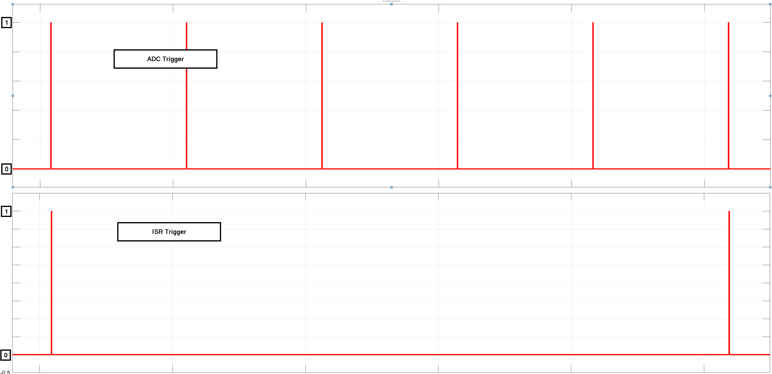
These settings result in the behavior depicted in Fig. 342 (ADC interrupt in the upper subplot, interrupt of R5 in the lower subplot):

Fig. 342 Resulting trigger ratio from the example above#
Warning
Trigger ratios other than
1were only tested with trigger sourceInterrupt_2L_minEspecially when using trigger sources with two ADC trigger events (e.g.
Interrupt_2L_max_min), the user has to take care of the resulting ADC/ISR trigger ratio
IP core#
The IP core takes up to 8 different interrupt sources as inputs (external port interrupts_in).
One of these inputs is selected by AXI configuration and routed directly routed to the interrupt_out_adc external port.
Additionally, all interrupt sources of interrupts_in are coupled with an internal counter that routes the signal of interrupts_in to interrupt_out_isr every n-th time the interrupt_out_adc signal is high.
Table Interface of uz_mux_axi IP core lists all input and output ports (AXI and external port) that are present in the IP core.
Port Name |
Port Type |
Data Type |
Target Platform Interfaces |
Range |
Unit |
Function |
|---|---|---|---|---|---|---|
interrupts_in |
Input |
uint8 |
External Signal |
interrupt input vector |
||
interrupt_out_adc |
Output |
bool |
External Signal |
ADC trigger signal |
||
interrupt_out_isr |
Output |
bool |
External Signal |
ISR trigger signal |
||
select_out |
Output |
ufix4 |
External Signal |
0-6 |
selected mux number |
|
select_AXI |
Input |
uint32 |
AXI4-Lite |
0-6 |
mux selector |
|
select_n_th_adc_interrupt |
Input |
uint32 |
AXI4-Lite |
1-255 |
ADC/ISR trigger ratio |
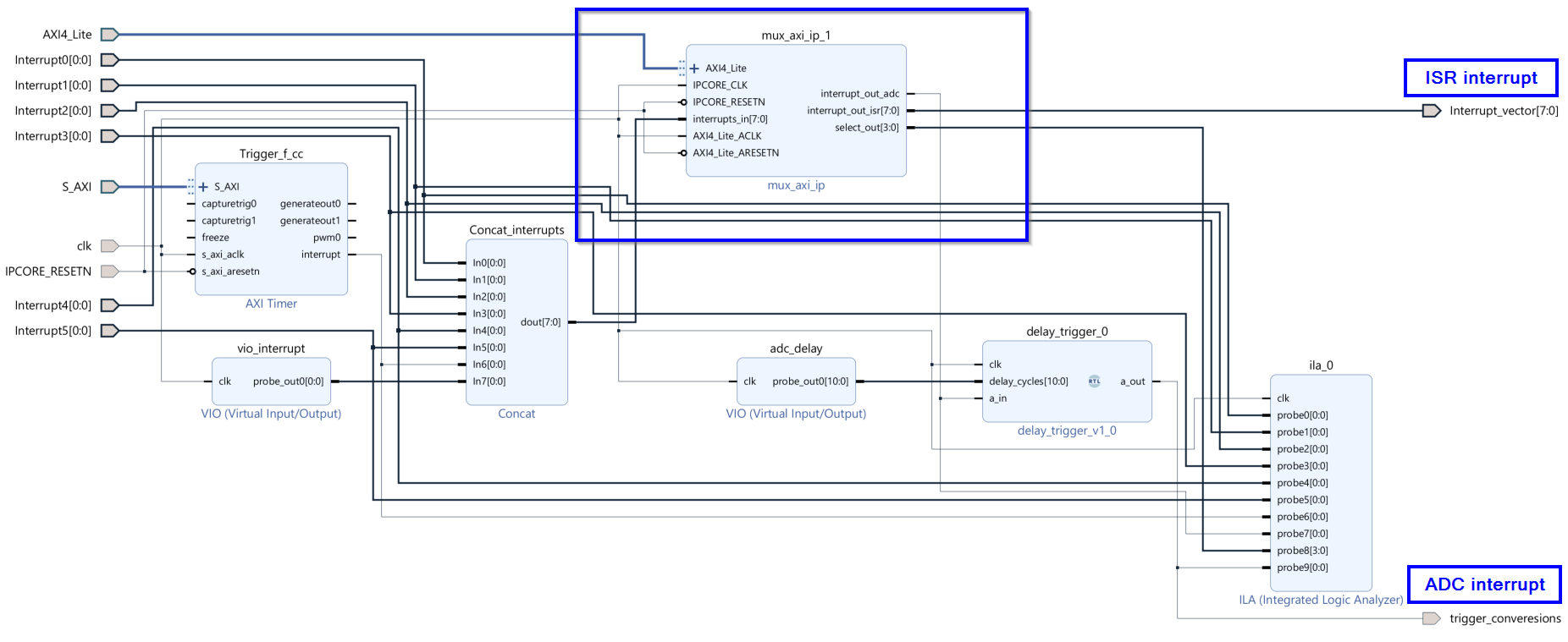
Fig. 343 of the IP core embedded in the block design:

Fig. 343 IP core in the default Vivado block design.#
Software driver#
The software driver is initialized by default. The user just has to select the mux and the interrupt ratio #define in uz_global_configuration.h
The IP core is initialized at the startup of the system. The software driver is not intended to change the settings at runtime.
Reference#
-
typedef struct uz_mux_axi_t uz_mux_axi_t#
Data type for object uz_mux_axi.
-
struct uz_mux_axi_config_t#
Configuration struct for uz_mux_axi.
-
uz_mux_axi_t *uz_mux_axi_init(struct uz_mux_axi_config_t config)#
Initializes an instance of the uz_mux_axi driver.
- Parameters:
config – Configuration values for the IP-Core
- Returns:
Pointer to initialized instance
-
void uz_mux_axi_enable(struct uz_mux_axi_t *self)#
Enables the instance of the uz_mux_axi IP-Core.
- Parameters:
self – Pointer to IP-Core instance that was initialized with init function
-
void uz_mux_axi_set_mux(struct uz_mux_axi_t *self, uint32_t mux)#
Sets the mux value (selects the interrupt source)
- Parameters:
self – Pointer to IP-Core instance that was initialized with init function
mux – Value of the selected mux (see uz_global_configuration.h)
-
void uz_mux_axi_set_n_th_interrupt(struct uz_mux_axi_t *self, uint32_t n_th_interrupt)#
Sets the n_th_interrupt value (sets the interrupt ratio between adc_interrupt/isr_interrupt)
- Parameters:
self – Pointer to IP-Core instance that was initialized with init function
n_th_interrupt – Value that sets the ratio between adc_interrupt and isr_interrupt