uz_dac_spi_interface#
The uz_dac_interface IP core takes input values for the uz_dac8831 DAC adapter card from the processor by AXI and writes them to the adapter card. The IP core is designed for simplicity. One AXI register for each DAC and a trigger conversion register is present. On a rising edge on the trigger conversion register (only possible by AXI), all values are written to all DACs. The SPI clk frequency can not be changed during runtime and is hard-coded to \(f_{SPI}=0.5 \cdot f_{IP-Core}\). The software driver features a conversion factor for each of the DAC channels to account for different gains in the OpAMP circuit of the card.
Software interface#
Example#
The following example initializes one driver instance and writes values to it. Note that the values of DAC1 and DAC8 are out of range for the +- 5V output and will clip accordingly. However, supplying out of range values does not trigger an assertion to be able to model the behavior of clipping sensors if they measure out-of-range values.
xparameters.h, gains are set to their nominal value in this case (2.0f).##include "uz_dac_interface.h"
#include "xparameters.h"
#include "uz_array.h"
struct uz_dac_interface_config_t dac_config={
.base_address=XPAR_UZ_USER_UZ_DAC_SPI_INTERFACE_0_BASEADDR, // Depends on xparameters.h!
.ip_clk_frequency_Hz=100000000,
.gain={2.0f,2.0f,2.0f,2.0f,2.0f,2.0f,2.0f,2.0f}
};
uz_dac_interface_t* dac_instance=uz_dac_interface_init(dac_config);
float dac_input[8]={-6.0f, -5.0f, -4.0f, -3.0f, 1.0f, 3.0f, 4.0f, 8.0f};
    uz_array_float_t dac_input_array={
    .data=&dac_input[0],
    .length=UZ_ARRAY_SIZE(dac_input)
};
uz_dac_interface_set_ouput_values(dac_instance,&dac_input_array);
Warning
The DAC always outputs the last value present in the DAC latch register. The user has to take care of safe DAC output states for the application before stopping control algorithms in the ISR or before flashing the MPSoC during testing.
Driver reference#
-
UZ_DAC_INTERFACE_OUTPUT_CHANNELS#
Defines the maximum number of DAC channels on the PCB. Has to be 8!
-
typedef struct uz_dac_interface_t uz_dac_interface_t#
Typedef for uz_dac_interface object definition.
-
struct uz_dac_interface_config_t#
Configuration struct for the DAC Interface IP-Core.
Public Members
-
uint32_t base_address#
Base address of the IP-Core instance to which the driver is coupled
-
uint32_t ip_clk_frequency_Hz#
Clock frequency of IP-Core
-
float gain[UZ_DAC_INTERFACE_OUTPUT_CHANNELS]#
Gain of the output OpAMPs of the DAC card. Usually set to 2.0f, but can be fine-tuned to match actual hardware.
-
uint32_t base_address#
-
uz_dac_interface_t *uz_dac_interface_init(struct uz_dac_interface_config_t config)#
Initializes an instance of the DAC driver.
- Parameters:
config – Config struct for the DAC
- Returns:
uz_dac_interface_t* Pointer to an instance of the driver
-
void uz_dac_interface_set_ouput_values(uz_dac_interface_t *self, uz_array_float_t *output_values)#
Writes the set-point to all DAC simultaneously. Saturates internally to allow for clipped operation.
- Parameters:
self – Pointer to driver instance
output_values – Array of set-point values
IP core interface (Vivado)#
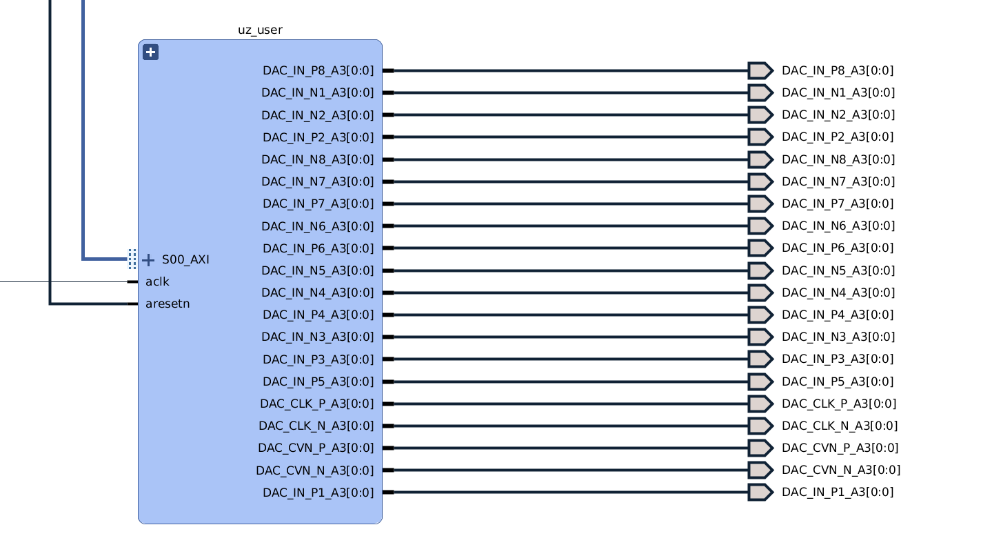
The FPGA interface of the IP core is a single signal while the uz_dac8831 PCB expects LVDS signals.
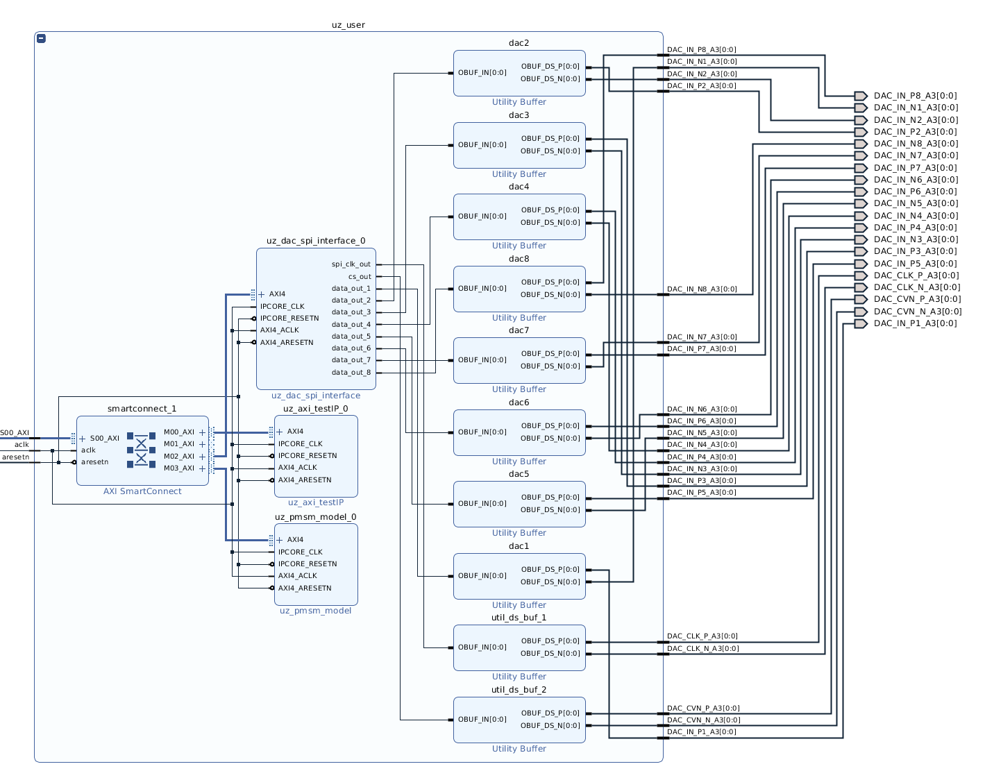
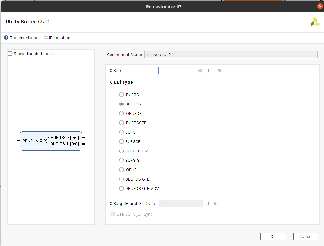
Therefore, additional Utility Buffers (with C Buf Type set to OBUFDS) have to be added to the Vivado block design between the output ports and the uz_dac_spi_interface IP core.
Constraints for using the DAC card uz_dac8831 in the slot A3 are supplied in the constraints folder (uz_dac8831_A3.xdc).
The SPI clk frequency of the IP core output is always half of the IP_CORE_CLK.
The IP core is only tested with IPCORE_CLK and AXI_ACLK connected to 100 MHz clock!

Fig. 374 Wiring to output ports.#

Fig. 375 Detailed setup of uz_dac_spi_interface IP Core and Utility Buffer#

Fig. 376 Settings of Utility Buffer#
Port Name |
Port type |
Data type |
Target Platform Interfaces |
Mapping |
Function |
|---|---|---|---|---|---|
trigger_write |
Inport |
boolean |
AXI4 |
x”100” |
Current values from data_out_1..8 are written output to SPI interface |
dac_data_1 |
Inport |
int16 |
AXI4 |
x”104” |
Data that should be sent to DAC1 |
dac_data_2 |
Inport |
int16 |
AXI4 |
x”108” |
Data that should be sent to DAC2 |
dac_data_3 |
Inport |
int16 |
AXI4 |
x”10C” |
Data that should be sent to DAC3 |
dac_data_4 |
Inport |
int16 |
AXI4 |
x”110” |
Data that should be sent to DAC4 |
dac_data_5 |
Inport |
int16 |
AXI4 |
x”114” |
Data that should be sent to DAC5 |
dac_data_6 |
Inport |
int16 |
AXI4 |
x”118” |
Data that should be sent to DAC6 |
dac_data_7 |
Inport |
int16 |
AXI4 |
x”11C” |
Data that should be sent to DAC7 |
dac_data_8 |
Inport |
int16 |
AXI4 |
x”120” |
Data that should be sent to DAC8 |
spi_clk_out |
Outport |
boolean |
External Port |
CLK for SPI interface of all DAC - to be connected to Utitlity buffer (OBUFDS) |
|
cs_out |
Outport |
boolean |
External Port |
CS for SPI interface of all DAC |
|
data_out_1 |
Outport |
boolean |
External Port |
Connection to DAC1 - to be connected to Utitlity buffer (OBUFDS) |
|
data_out_2 |
Outport |
boolean |
External Port |
Connection to DAC2 - to be connected to Utitlity buffer (OBUFDS) |
|
data_out_3 |
Outport |
boolean |
External Port |
Connection to DAC3 - to be connected to Utitlity buffer (OBUFDS) |
|
data_out_4 |
Outport |
boolean |
External Port |
Connection to DAC4 - to be connected to Utitlity buffer (OBUFDS) |
|
data_out_5 |
Outport |
boolean |
External Port |
Connection to DAC5 - to be connected to Utitlity buffer (OBUFDS) |
|
data_out_6 |
Outport |
boolean |
External Port |
Connection to DAC6 - to be connected to Utitlity buffer (OBUFDS) |
|
data_out_7 |
Outport |
boolean |
External Port |
Connection to DAC7 - to be connected to Utitlity buffer (OBUFDS) |
|
data_out_8 |
Outport |
boolean |
External Port |
Connection to DAC8 - to be connected to Utitlity buffer (OBUFDS) |
References#
Data sheet of DAC8831: https://www.ti.com/lit/ds/slas449d/slas449d.pdf?ts=1653291212982