Temperature Card IP Core V1#
Detailed Description#
This IP core is designed for the LTC2983 temperature measurement system. With the ability to measure different sensor types and built-in data preparation, this card extends the functionality of the UltraZohm. The total amount of 60-Channels (40 on the frontpanel, 20 internal) could be wired directly on the card or in the plug for different kind of sensors. The documentation for the Temperature Card can be e.g. found under Temperature Card Rev02 or newer.
IP Core#
The temperature card is provided with an IP core, which handles the configuration, triggers periodical measurements, and provides the results that are collected afterwards by the software driver. The figure below shows the IP core in a Vivado block design environment.
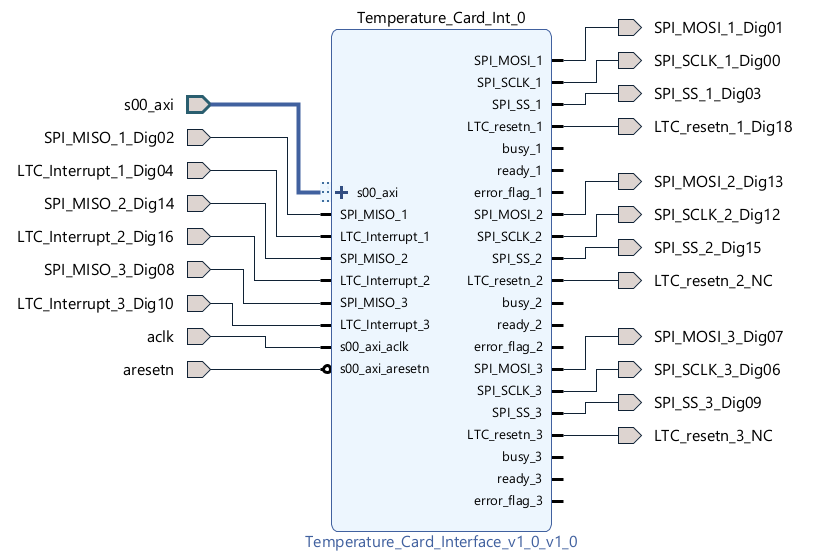
Fig. 481 IP Core Temperature Card V1#
Depending on the physical adapter board slot that you are using for the adapter board, the IP core has to be connected to the pins of the proper adapter board slot.
Here it is shown at the example of adapter board slot D4, where _Ch4 refers to adapter board slot D4. Pay attention
that no other pins regarding _Ch4 are present in the block design. Delete them to avoid errors during the build or damage to the hardware. Since all three channelgroups A-C share the common
reset signal LTC_resetn_1, all other reset signals are left unconnected. For a more detailed description on how to implement the IP core into your block design, refer to Temperature Card Rev02.
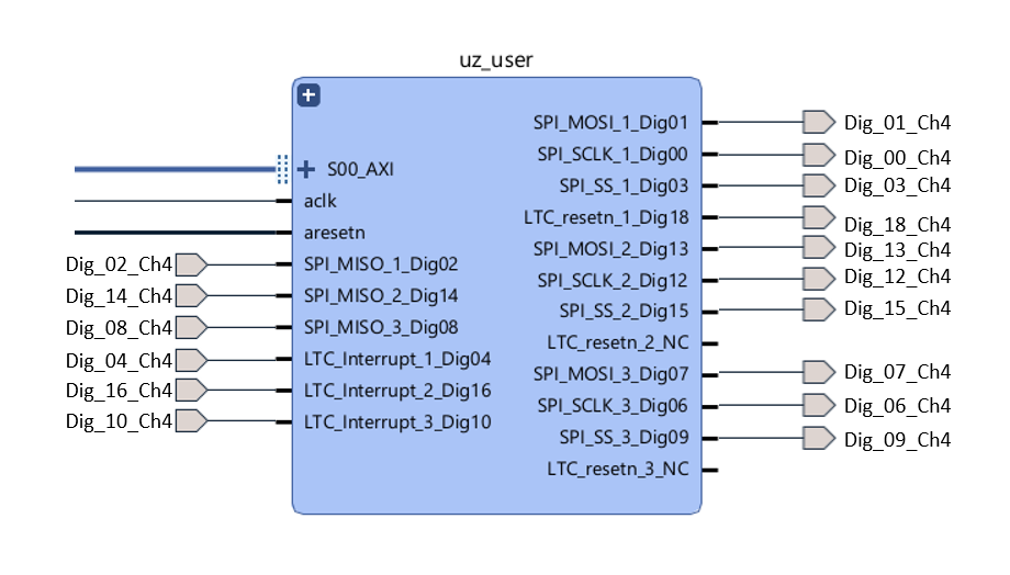
Fig. 482 Pinout and connection to correct pins at the example of adapter board slot D4#
Software Driver#
The LTC2983 is a powerful and complex temperature measurement IC. Since this documentation cannot cover all possible use-cases, just some relevant and specific ones are highlighted
within the scope of this page. In particular, two examples are provided that match the existing assembly variants of the PCB repository, Thermocouples Type K and PT100 resistance temperature detectors (RTD`s).
The driver is structured in order to reflect the underlying hardware with its three channelgroups A-C. Within each channelgroup there are 20 Channels 00-19 that have to be configured and where
results can be read from. An easy way to get the configuration-words for each channel is provided with fixed #defines.
Inside the uz_temperaturecard.h the defines from Analog Devices (producer of the LTC2983) are present.
With those defines, simply use bitwise-or to create the configuration-word for different kind of sensors or use examples below.
It is necessary to read the datasheet of the LTC2983 carefully, especially page 16 to 54 for understanding how the LTC2983 needs to be configured when not using provided examples.
Regardless of what type of sensor configuration you want to use, some general steps for creating an instance of the IP core driver are similar for all use-cases.
Below the necessary steps are shown at the example of one temperature adapter board mounted in adapter board slot D4.
In Vitis, in the Baremetal project under
src/uz/open the fileuz_global_configuration.hand make sure, that the maximum allowed instances define for this driver is at least1U
// Configuration defines for the number of used instances
...
#define UZ_TEMPERATURE_CARD_MAX_INSTANCES               1U
...
In Vitis, in the Baremetal project under the folder
hw_initcreate a new fileuz_temperature_card_init.cInclude necessary files and create a
configstruct as well as an init function for one instance:
#include "../include/uz_temperature_card_init.h"
#include "../uz/uz_HAL.h"
#include "../uz/uz_global_configuration.h"
#include "xparameters.h"

  struct uz_temperaturecard_config_t config_temperature_card = {
  // general config
  .base_address = XPAR_UZ_USER_TEMPERATURE_CARD_INT_0_BASEADDR,
  .ip_clk_frequency_Hz = 100000000U,
  .Sample_Freq_Hz = 5U, // we are fine with 5 Hz since the LTC2983 itself isn't that fast with updating the results
  // channelgroup A
  .Configdata_A = {0U}, // for proper configuration we will come back later
  // channelgroup B
  .Configdata_B = {0U},
  // channelgroup C
  .Configdata_C = {0U}
  };

uz_temperaturecard_t* initialize_temperature_card_d4(void){
       return (uz_temperaturecard_init(config_temperature_card));
}
In the
includefolder, create a header fileuz_temperature_card_init.hInclude necessary files and the function prototype of your init routine:
#pragma once
#include "../IP_Cores/uz_temperaturecard/uz_temperaturecard.h"

uz_temperaturecard_t* initialize_temperature_card_d4(void);
In the Global_Data header file
globalData.h, include necessary header and add an object pointer of the respective type in theobject_pointer_tstruct, as well as channelgroup data structs to theactualValues:
...
#include "IP_Cores/uz_temperaturecard/uz_temperaturecard.h"
...

typedef struct{
...
uz_temperaturecard_t* temperature_card_d4;
...
}object_pointers_t;

typedef struct _actualValues_ {
...
uz_temperaturecard_OneGroup channel_A_data;
uz_temperaturecard_OneGroup channel_B_data;
uz_temperaturecard_OneGroup channel_C_data;
...
} actualValues;
In
main.c, initialize an instance of the driver and assign it to the object pointer structure in the Global_Data inside theinit_ip_corescase. AlsoResetandStartthe IP core by calling respective functions:
...
case init_ip_cores:
...
Global_Data.objects.temperature_card_d4 = initialize_temperature_card_d4();
uz_TempCard_IF_Reset(Global_Data.objects.temperature_card_d4);
uz_TempCard_IF_Start(Global_Data.objects.temperature_card_d4);
...
break;
In
main.h, include your init header file#include "include/uz_temperature_card_init.h".In
isr.c, now you can read the result values of the IP Core and use them:
...
uz_TempCard_IF_MeasureTemps_cyclic(Global_Data.objects.temperature_card_d4);
Global_Data.av.channel_A_data = uz_TempCard_IF_get_channel_group(Global_Data.objects.temperature_card_d4, 'A');
Global_Data.av.channel_B_data = uz_TempCard_IF_get_channel_group(Global_Data.objects.temperature_card_d4, 'B');
Global_Data.av.channel_C_data = uz_TempCard_IF_get_channel_group(Global_Data.objects.temperature_card_d4, 'C');
...
E.g.
Global_Data.av.channel_A_data.temperature[4]will contain the temperature in degrees celsius ofCh5ofChannelGroup A.
The function uz_TempCard_IF_MeasureTemps_cyclic updates one channel per call, and uses an incremental pointer internally.
To update every channel of the TemperatureCard, 60 calls are needed, since every ChannelGroup has 20 channels.
For each LTC2983 (ChannelGroup) on the temperature card, the uz_temperaturecard_OneGroup contains the configuration, raw-values, temperature values and also error indicators for each channel.
This allows the user a comprehensive use of the measured values with some manual implementations.
The driver will perform a small check if the measurement is valid and calculate the temperature value from the raw value and stores the results in the temperature-array inside the group.
Note
If the measurement is not valid, the results in the temperature-array is fixed to the impossible value of -333.3f.
Configuration Examples#
Following, some example applications and respective configurations, hardware- and software-wise are presented.
As you might remember from the above steps, we left the .Configdata_ A-C all ={0U}, and therefore, unconfigured.
The above steps are mandatory for all use-cases. Below the configuration for the specific use-cases for the specific assembly variants of the PCB are described.
16x Type K Thermocouple at ChannelGroup A#
This example shows how to read 16 Type K thermocouples connected to ChannelGroup A, using the temperature card in addition
with an external connector box, designed for Type K thermocouples.
PCB assembly variant#
The figure below shows the temperature adapter board Rev03 with assembly variant All_Thermocouple.
The main characteristics of this assembly variant are highlighted.
In this variant, channel groups A to C are equipped for single-ended thermocouple measurement at Ch05 to Ch20 and each channel group has
an own cold junction compensation (CJC), using a PT100 sensor, located in the external connector box. Together with a necessary sense resistor,
the CJC is connected to Ch1 to Ch4 of the LTC2983 of each channel group.
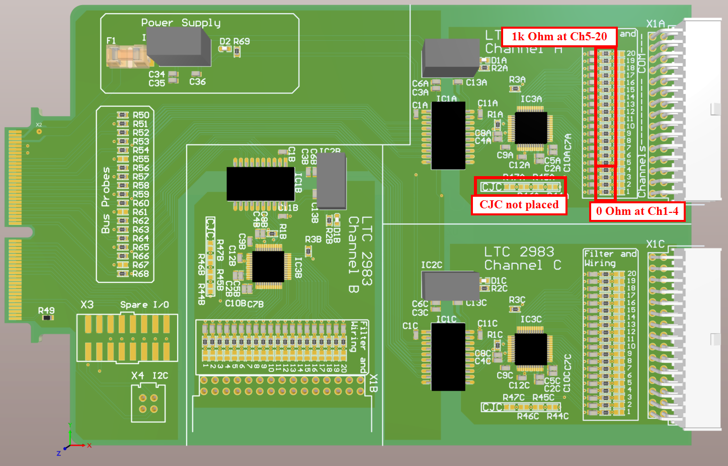
Fig. 483 uz_d_temperaturecard_ltc2983, Rev03, assembly variant: All_Thermocouple#
External connector box#
- The external box shown below consists of mainly three components.
The
uz_per_thermocoupler_connectorPCBThe housing:
Fischer Elektronik AKG 165 038 100 SA(with customized cutouts, see CAD data in the PCB repo ofuz_per_thermocoupler_connector)Pre-assembled cable
Samtec MMSD-15-xxx-x-xx.xx-D-P-LDXfor connecting the external box to one of the ChannelGroup connectors

Fig. 484 Front view of the external box.#
The numbers above the Type K connectors refer to the array entry number in the variable float temperature[20] in struct uz_temperaturecard_OneGroup, that
holds the results of the 20 measurement channels of each channel group. Since Ch1 to Ch4 (respectively array entry 0 to 3) are used for the cold junction compensation
measurement, Ch5 (array index 04) is the first channel number to be used for TypeK sensors.
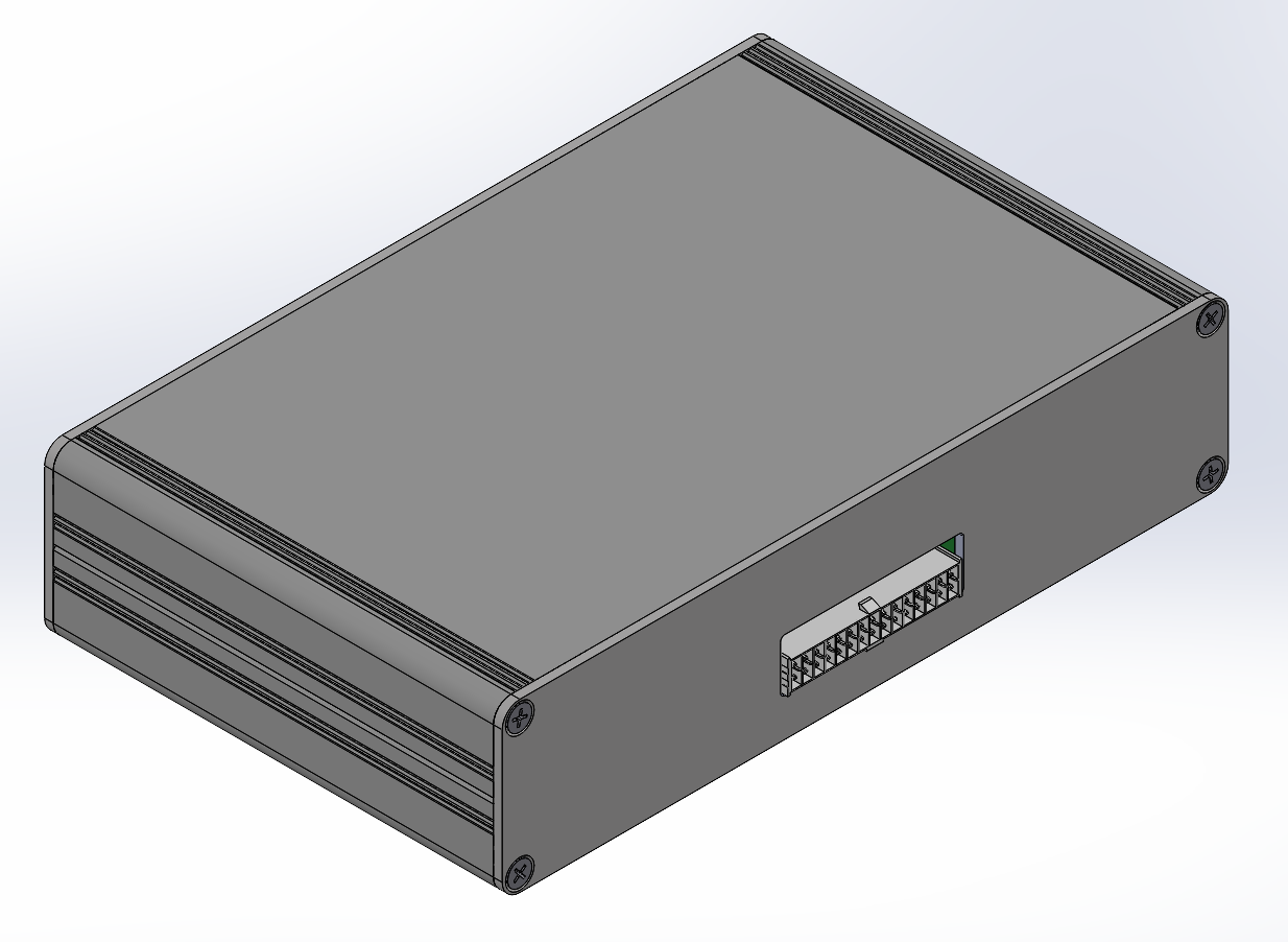
Fig. 485 Rear view of the external box#
Software driver configuration#
 struct uz_temperaturecard_config_t config_temperature_card = {
 // general config
 .base_address = XPAR_UZ_USER_TEMP_CARD_INTERFACE_TEMPERATURE_CARD_INT_0_BASEADDR,
 .ip_clk_frequency_Hz = 100000000U,
 .Sample_Freq_Hz = 5U,
 // channelgroup A
 .Configdata_A = {0U},
 .Configdata_A[0] = 0U,
 .Configdata_A[1] = SENSOR_TYPE__SENSE_RESISTOR | SENSE_RESISTOR_VALUE_1k,
 .Configdata_A[2] = 0U,
 .Configdata_A[3] = SENSOR_TYPE__RTD_PT_100 | RTD_RSENSE_CHANNEL__2 | RTD_NUM_WIRES__2_WIRE | RTD_EXCITATION_MODE__NO_ROTATION_SHARING | RTD_EXCITATION_CURRENT__100UA | RTD_STANDARD__EUROPEAN,
 .Configdata_A[4] = SENSOR_TYPE__TYPE_K_THERMOCOUPLE | TC_COLD_JUNCTION_CH__4 | TC_SINGLE_ENDED | TC_OPEN_CKT_DETECT__NO,
 .Configdata_A[5] = SENSOR_TYPE__TYPE_K_THERMOCOUPLE | TC_COLD_JUNCTION_CH__4 | TC_SINGLE_ENDED | TC_OPEN_CKT_DETECT__NO,
 .Configdata_A[6] = SENSOR_TYPE__TYPE_K_THERMOCOUPLE | TC_COLD_JUNCTION_CH__4 | TC_SINGLE_ENDED | TC_OPEN_CKT_DETECT__NO,
 .Configdata_A[7] = SENSOR_TYPE__TYPE_K_THERMOCOUPLE | TC_COLD_JUNCTION_CH__4 | TC_SINGLE_ENDED | TC_OPEN_CKT_DETECT__NO,
 .Configdata_A[8] = SENSOR_TYPE__TYPE_K_THERMOCOUPLE | TC_COLD_JUNCTION_CH__4 | TC_SINGLE_ENDED | TC_OPEN_CKT_DETECT__NO,
 .Configdata_A[9] = SENSOR_TYPE__TYPE_K_THERMOCOUPLE | TC_COLD_JUNCTION_CH__4 | TC_SINGLE_ENDED | TC_OPEN_CKT_DETECT__NO,
 .Configdata_A[10] = SENSOR_TYPE__TYPE_K_THERMOCOUPLE | TC_COLD_JUNCTION_CH__4 | TC_SINGLE_ENDED | TC_OPEN_CKT_DETECT__NO,
 .Configdata_A[11] = SENSOR_TYPE__TYPE_K_THERMOCOUPLE | TC_COLD_JUNCTION_CH__4 | TC_SINGLE_ENDED | TC_OPEN_CKT_DETECT__NO,
 .Configdata_A[12] = SENSOR_TYPE__TYPE_K_THERMOCOUPLE | TC_COLD_JUNCTION_CH__4 | TC_SINGLE_ENDED | TC_OPEN_CKT_DETECT__NO,
 .Configdata_A[13] = SENSOR_TYPE__TYPE_K_THERMOCOUPLE | TC_COLD_JUNCTION_CH__4 | TC_SINGLE_ENDED | TC_OPEN_CKT_DETECT__NO,
 .Configdata_A[14] = SENSOR_TYPE__TYPE_K_THERMOCOUPLE | TC_COLD_JUNCTION_CH__4 | TC_SINGLE_ENDED | TC_OPEN_CKT_DETECT__NO,
 .Configdata_A[15] = SENSOR_TYPE__TYPE_K_THERMOCOUPLE | TC_COLD_JUNCTION_CH__4 | TC_SINGLE_ENDED | TC_OPEN_CKT_DETECT__NO,
 .Configdata_A[16] = SENSOR_TYPE__TYPE_K_THERMOCOUPLE | TC_COLD_JUNCTION_CH__4 | TC_SINGLE_ENDED | TC_OPEN_CKT_DETECT__NO,
 .Configdata_A[17] = SENSOR_TYPE__TYPE_K_THERMOCOUPLE | TC_COLD_JUNCTION_CH__4 | TC_SINGLE_ENDED | TC_OPEN_CKT_DETECT__NO,
 .Configdata_A[18] = SENSOR_TYPE__TYPE_K_THERMOCOUPLE | TC_COLD_JUNCTION_CH__4 | TC_SINGLE_ENDED | TC_OPEN_CKT_DETECT__NO,
 .Configdata_A[19] = SENSOR_TYPE__TYPE_K_THERMOCOUPLE | TC_COLD_JUNCTION_CH__4 | TC_SINGLE_ENDED | TC_OPEN_CKT_DETECT__NO,
 // channelgroup B
 .Configdata_B = {0U},
 // channelgroup C
 .Configdata_C = {0U}
 };
As can be seen, we now assigned configuration words for almost every of the 20 channels of ChannelGroup A. Each configuration word is created by
bit-wise OR of several #defines. Ch2 (array index 1) is configured for being connected to a 1kOhm sense resistor, that the LTC2983 uses for measuring its
excitation current of the PT100 RTD that is connected to Ch4 (array index 3), and is excited with a 100µA current. This PT100 serves as the CJC measurement device for
the Thermocouples. The 16 remaining channels Ch5 to Ch20 are configured for single-ended Type K thermocouples that refer to Ch4 for internal CJC within the LTC2983.
With this, the user is able to simply read the temperature results in degrees celsius directly from the float temperature[20] variable in struct uz_temperaturecard_OneGroup as mentioned
at the beginning of the driver section.
Note
If fewer channels than 16 are sufficient for your application, set the not necessary channels in the config_temperature_card struct to 0U.
Since the LTC2983 updates all configured channels within one ChannelGroup one after another, fewer configured channels will lead to a faster
update rate of the measurements!
9x 2-wire PT100 at ChannelGroup A#
In this example the temperature card is used to read nine winding temperatures from an electric machine which uses PT100 sensors.
Since the mean value is of interest and non-valid values (e.g. due to EMI) should not make the average unusable, the averaging function of the driver is used.
Besides the necessary sense resistor for the LTC2983, the 2-wire PT100 RTD`s are connected to channels Ch3 - Ch4, Ch5 - Ch6 and so on.
PCB assembly variant#
The figure below shows the temperature adapter board Rev03 with assembly variant All_2wire_RTD.
The main characteristics of this assembly variant are highlighted.
In this variant, channel groups A to C are equipped for 2-wire RTD measurement at channels Ch3 - Ch4, Ch5 - Ch6 and so on
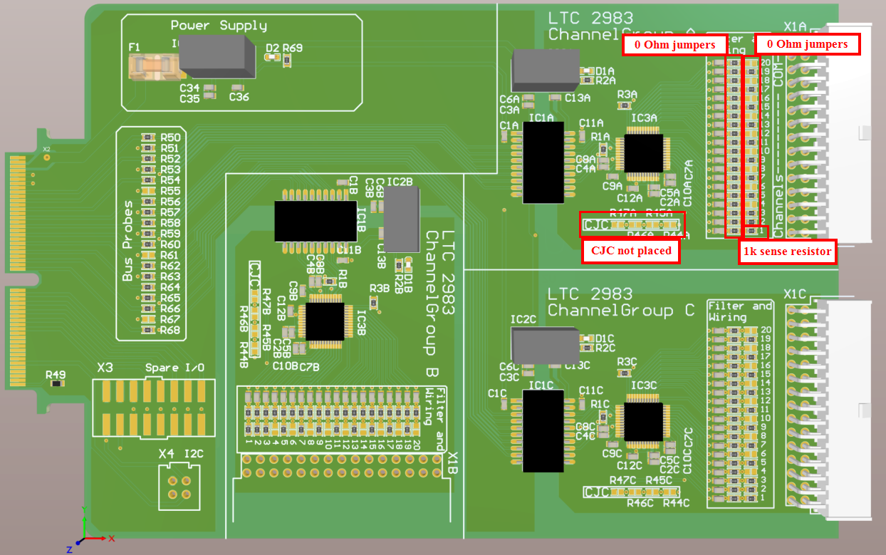
Fig. 486 uz_d_temperaturecard_ltc2983, Rev03, assembly variant: All_2wire_RTD#
Software driver configuration#
 struct uz_temperaturecard_config_t config_temperature_card = {
 // general config
 .base_address = XPAR_UZ_USER_TEMP_CARD_INTERFACE_TEMPERATURE_CARD_INT_0_BASEADDR,
 .ip_clk_frequency_Hz = 100000000U,
 .Sample_Freq_Hz = 5U,
 // channelgroup A
 .Configdata_A = {0U},
 .Configdata_A[0]  = 0U,
 .Configdata_A[1]  = SENSOR_TYPE__SENSE_RESISTOR | SENSE_RESISTOR_VALUE_1k,
 .Configdata_A[2]  = 0U,
 .Configdata_A[3]  = SENSOR_TYPE__RTD_PT_100 | RTD_RSENSE_CHANNEL__2 | RTD_NUM_WIRES__2_WIRE | RTD_EXCITATION_MODE__NO_ROTATION_SHARING | RTD_EXCITATION_CURRENT__100UA | RTD_STANDARD__EUROPEAN,
 .Configdata_A[4]  = 0U,
 .Configdata_A[5]  = SENSOR_TYPE__RTD_PT_100 | RTD_RSENSE_CHANNEL__2 | RTD_NUM_WIRES__2_WIRE | RTD_EXCITATION_MODE__NO_ROTATION_SHARING | RTD_EXCITATION_CURRENT__100UA | RTD_STANDARD__EUROPEAN,
 .Configdata_A[6]  = 0U,
 .Configdata_A[7]  = SENSOR_TYPE__RTD_PT_100 | RTD_RSENSE_CHANNEL__2 | RTD_NUM_WIRES__2_WIRE | RTD_EXCITATION_MODE__NO_ROTATION_SHARING | RTD_EXCITATION_CURRENT__100UA | RTD_STANDARD__EUROPEAN,
 .Configdata_A[8]  = 0U,
 .Configdata_A[9]  = SENSOR_TYPE__RTD_PT_100 | RTD_RSENSE_CHANNEL__2 | RTD_NUM_WIRES__2_WIRE | RTD_EXCITATION_MODE__NO_ROTATION_SHARING | RTD_EXCITATION_CURRENT__100UA | RTD_STANDARD__EUROPEAN,
 .Configdata_A[10]  = 0U,
 .Configdata_A[11] = SENSOR_TYPE__RTD_PT_100 | RTD_RSENSE_CHANNEL__2 | RTD_NUM_WIRES__2_WIRE | RTD_EXCITATION_MODE__NO_ROTATION_SHARING | RTD_EXCITATION_CURRENT__100UA | RTD_STANDARD__EUROPEAN,
 .Configdata_A[12]  = 0U,
 .Configdata_A[13] = SENSOR_TYPE__RTD_PT_100 | RTD_RSENSE_CHANNEL__2 | RTD_NUM_WIRES__2_WIRE | RTD_EXCITATION_MODE__NO_ROTATION_SHARING | RTD_EXCITATION_CURRENT__100UA | RTD_STANDARD__EUROPEAN,
 .Configdata_A[14]  = 0U,
 .Configdata_A[15] = SENSOR_TYPE__RTD_PT_100 | RTD_RSENSE_CHANNEL__2 | RTD_NUM_WIRES__2_WIRE | RTD_EXCITATION_MODE__NO_ROTATION_SHARING | RTD_EXCITATION_CURRENT__100UA | RTD_STANDARD__EUROPEAN,
 .Configdata_A[16]  = 0U,
 .Configdata_A[17] = SENSOR_TYPE__RTD_PT_100 | RTD_RSENSE_CHANNEL__2 | RTD_NUM_WIRES__2_WIRE | RTD_EXCITATION_MODE__NO_ROTATION_SHARING | RTD_EXCITATION_CURRENT__100UA | RTD_STANDARD__EUROPEAN,
 .Configdata_A[18]  = 0U,
 .Configdata_A[19] = SENSOR_TYPE__RTD_PT_100 | RTD_RSENSE_CHANNEL__2 | RTD_NUM_WIRES__2_WIRE | RTD_EXCITATION_MODE__NO_ROTATION_SHARING | RTD_EXCITATION_CURRENT__100UA | RTD_STANDARD__EUROPEAN,
 // channelgroup B
 .Configdata_B = {0U},
 // channelgroup C
 .Configdata_C = {0U}
 };
As can be seen, we now assigned configuration words for almost every of the 20 channels of ChannelGroup A. Each configuration word is created by
bit-wise OR of several #defines. Ch2 (array index 1) is configured for being connected to a 1kOhm sense resistor, that the LTC2983 uses for measuring its
excitation current of the PT100 RTD`s. The excitation current is set to 100µA.The 18 remaining channels Ch3 to Ch20 are configured for nine 2-wire PT100 RTD`s.
With this, the user is able to simply read the temperature results in degrees celsius directly from the float temperature[20] variable in struct uz_temperaturecard_OneGroup as mentioned
at the beginning of the driver section.
Note
If fewer channels than 9 are sufficient for your application, set the not necessary channels in the config_temperature_card struct to 0U.
Since the LTC2983 updates all configured channels within one ChannelGroup one after another, fewer configured channels will lead to a faster
update rate of the measurements!
Averaging of Temperature Channels#
In addition to just readout the temperature values, in this example we are interested into the average temperature over all valid channels. For this purpose the driver offers a function that handles this. The example below shows how to use the averaging function for all 9 2-wire RTD`s of ChannelGroup A:
 // pre-loop
 float average = 0.0f;

 // in isr
  ...
  uz_TempCard_IF_MeasureTemps_cyclic(Global_Data.objects.temperature_card_d4);
  Global_Data.av.channel_A_data = uz_TempCard_IF_get_channel_group(Global_Data.objects.temperature_card_d4, 'A');
  Global_Data.av.channel_B_data = uz_TempCard_IF_get_channel_group(Global_Data.objects.temperature_card_d4, 'B');
  Global_Data.av.channel_C_data = uz_TempCard_IF_get_channel_group(Global_Data.objects.temperature_card_d4, 'C');
  average = uz_TempCard_IF_average_temperature_for_valid(Global_Data.av.channel_A_data, 0U, 19U);
  ...
Driver Reference#
-
typedef struct uz_temperaturecard_t uz_temperaturecard_t#
Data type for object uz_temperaturecard.
-
struct uz_temperaturecard_config_t#
Configuration struct for TemperatureCard-IP.
Public Members
-
uint32_t Sample_Freq_Hz#
Sampling frequency (Hz) to trigger a temperature measurement. Must be greater 0U
-
uint32_t Config_Global_A#
GlobalConfig-Register for Channel A
-
uint32_t Config_Mux_A#
MuxDelay-Register for Channel A
-
uint32_t Config_Global_B#
GlobalConfig-Register for Channel A
-
uint32_t Config_Mux_B#
MuxDelay-Register for Channel A
-
uint32_t Config_Global_C#
GlobalConfig-Register for Channel A
-
uint32_t Config_Mux_C#
MuxDelay-Register for Channel A
-
uint32_t Configdata_A[20]#
Configuration-struct for the first 20-Channels / Channelgroup A
-
uint32_t Configdata_B[20]#
Configuration-struct for the second 20-Channels / Channelgroup B
-
uint32_t Configdata_C[20]#
Configuration-struct for the last 20-Channels / Channelgroup C
-
uint32_t Sample_Freq_Hz#
-
struct uz_temperaturecard_OneGroup#
Data type for object uz_temperaturecard_OneGroup.
Public Members
-
float temperature[20]#
calculated value for the Temperature Channelgroup
-
uint32_t temperature_raw[20]#
raw value for the Temperature Channelgroup
-
uint32_t Configdata[20]#
used Config for the Temperature Channelgroup
-
uint32_t Channel_Fault_Data[20]#
Holds Fault Data of the respective channels 1U=valid, for error descriptions see datasheet
-
float temperature[20]#
Operation#
-
uz_temperaturecard_t *uz_temperaturecard_init(struct uz_temperaturecard_config_t config)#
Initializes an instance of the temperaturecard driver.
- Parameters:
config – Configuration values for the IP-Core
- Returns:
Pointer to initialized instance
-
void uz_TempCard_IF_Reset(uz_temperaturecard_t *self)#
Resets the whole TemperatureCard-IP. This should be used after the init of the IP-Core to update the LTC2983.
- Parameters:
self – Pointer to driver instance
-
void uz_TempCard_IF_Start(uz_temperaturecard_t *self)#
Starts the TemperatureCard-IP.
- Parameters:
self – Pointer to driver instance
-
void uz_TempCard_IF_Stop(uz_temperaturecard_t *self)#
Starts the TemperatureCard-IP.
- Parameters:
self – Pointer to driver instance
-
void uz_TempCard_IF_MeasureTemps_cyclic(uz_temperaturecard_t *self)#
Reads one Temperature-Channel of the IP-Core and updates the dedicated Temperature-Data of the the instance. To Update the whole Temperature-Data of the instance, multiple calls equal the Channel-amount (60) are needed. Can be used inside the ISR.
- Parameters:
self – Pointer to driver instance
-
float uz_TempCard_IF_get_channel(uz_temperaturecard_t *self, const char channelgroup, uint32_t channel)#
Reads the temperatures and additional data from one specified channel.
- Parameters:
self – Pointer to driver instance
channelgroup – specify channelgroup to read as char, e.g. ‘a’, ‘b’, ‘c’ (capital letters are also possible)
channel – specify channel from 0 to 19
- Returns:
Temperature of the specific channel in the specific channelgroup
-
float uz_TempCard_IF_average_temperature_for_valid(uz_temperaturecard_OneGroup channeldata, const uint32_t lower, const uint32_t upper)#
Averages all valid channels in the specified range. If one channel gets invalid during measurement, average will not be affected since it will no longer be included in the calculation.
- Parameters:
channeldata – Data for the group of channels
lower – lowest channel to include (minimum 0)
upper – highest channel to include (maximum 19)
- Returns:
average of all valid temperatures in specified channel range
Designed by#
Robert Zipprich (Universität Kassel / EMA) // Michael Hoerner, Valentin Hoppe (TH Nürnberg) in 01/2023