Digital Encoder 1v00#
Source#
Functionality#
Supports the following encoder types:
Resolver: Fully integrated Resolver controller with excitation signal generation, serial interface and optional absolute encoder emulation (shared with one digital hall channel)
Digital Hall: Differential or single ended hall signals
Incremental Encoder: Differential or single ended incremental encoder
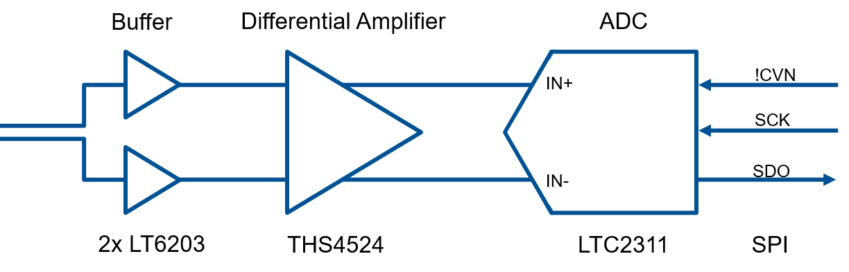
Analog Hall: Four differential analog channels, three on RJ45 connector, one on header, serial communication to ADCs
Absolute Encoder: Hardware compatible to SSI, BiSS and others
Detailed Description#
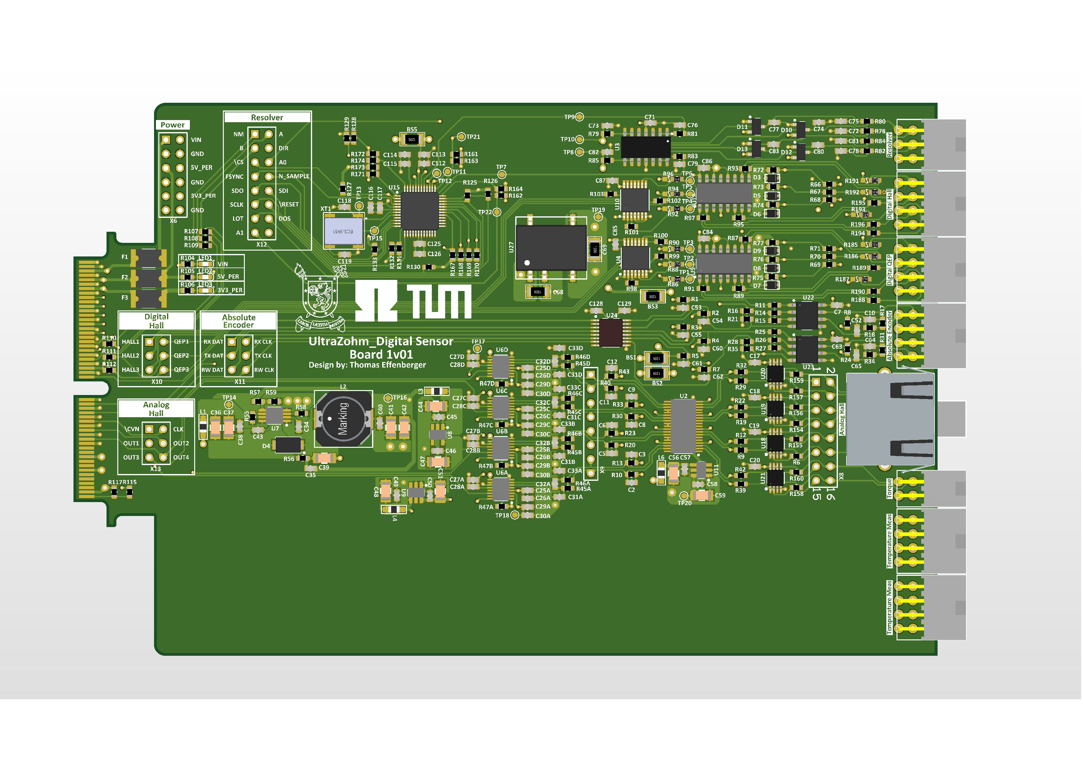
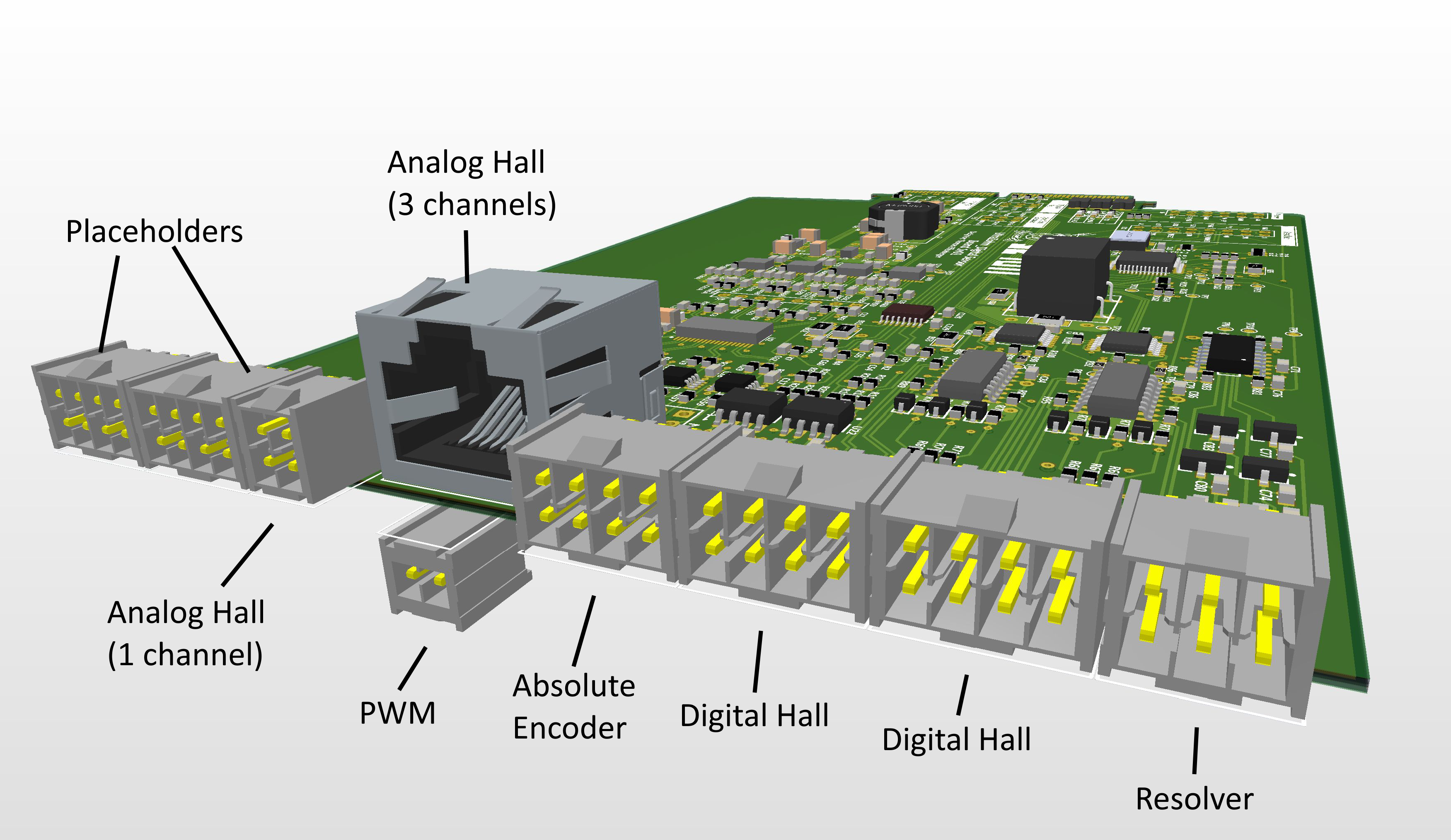
The UltraZohm Sensor Board features a variety of different industrial standard interfaces. This makes the board the perfect solution for flexible use in testing environments. It supports incremental encoders, resolvers, analog and digital hall sensors as well es absolute encoders via serial connection. Most of the interfaces can be used simultaneously, which allows for either using many sensors in parallel or for evaluating different sensor systems at once. With many placement options the sensor board can be customized to serve the needs of specific applications.
Before first use#
Determine correct placement options for correct function
Program CPLDs with firmware, see Programming the CPLD for details
Known issues#
none
Compatibility#
The first version is compatible with slots D1-D4. The next revision is intended to be used in slot D5.
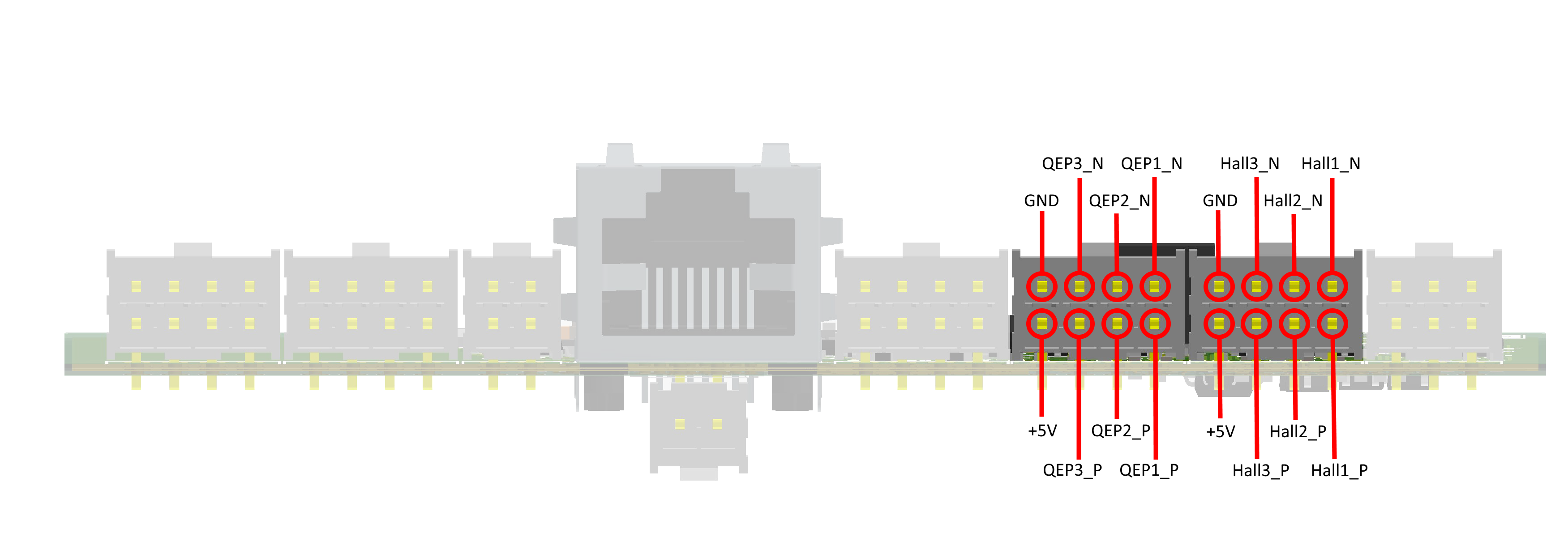
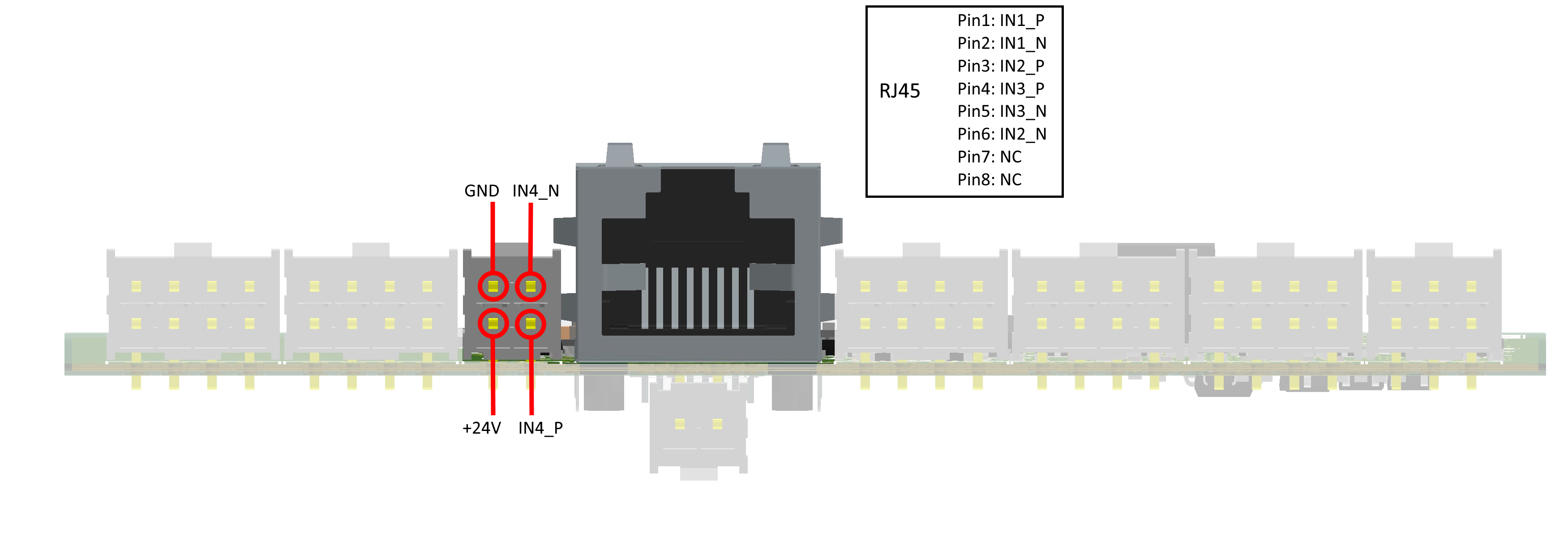
Pinout#
Interfaces in Detail#
Resolver#
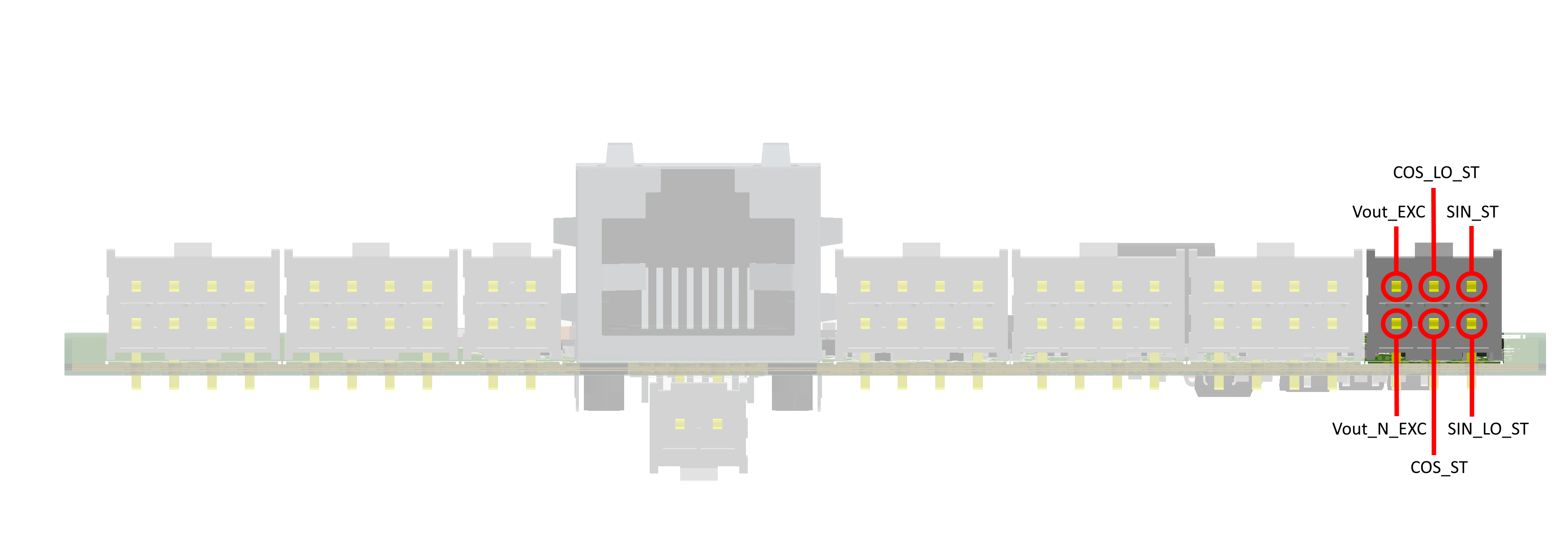
The resolver interface is equipped with AD2S1210 from Analog Devices. It features excitation signal generation, 10-/12-/14-/16-bit resolution ADC, SPI or parallel interface (currently only SPI is supported), incremental encoder emulation and simple configuration by pull-up/pull-down choices. The devices works in one of three modes selectable by hardware inputs A0 and A1. In position mode, the corresponding data can be obtained directly by toggling the clock line without sending register addresses first. The same applies for velocity mode. Those two are also called normal modes. In the third mode, the configuration mode, allows for further access on the devices registers and configuration. In this mode it is possible to change the excitation frequency or also read back position and velocity data. Only in this mode the ADC resolution can be changed, ignoring the external resistor configuration.
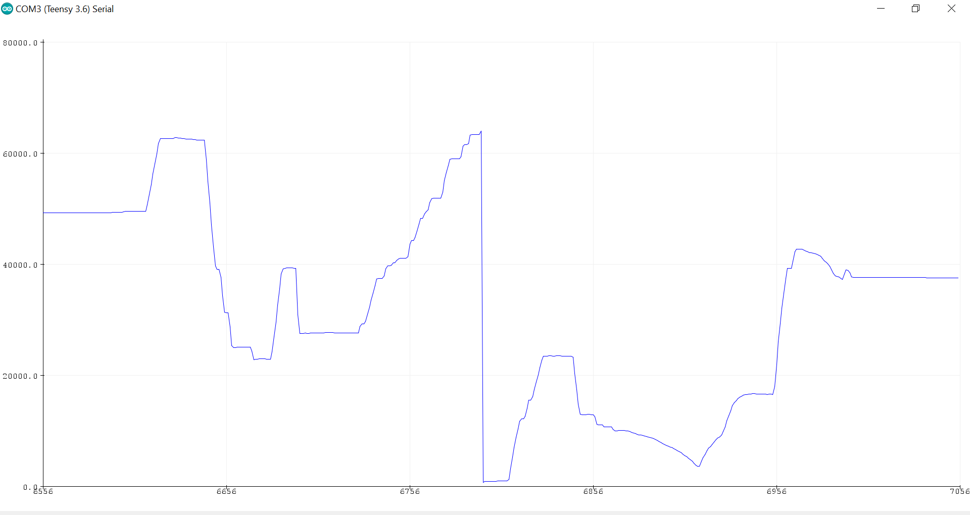
Fig. 262 Position Data from Resolver#
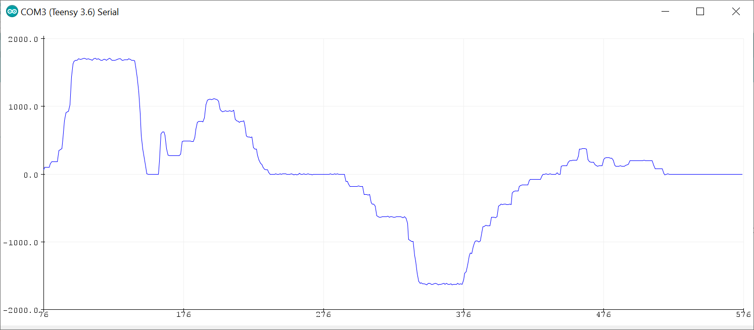
Fig. 263 Velocity Data from Resolver#
When communicating with the controller, attention has to be paid on the SPI mode. The correct one is MODE1 with clock polarity idle low and clock phase one meaning falling edge.
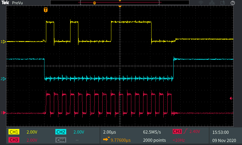
Fig. 264 Data Transmission in normal mode (position or velocity), yellow: MISO, blue: FSYNC, red: CLK#
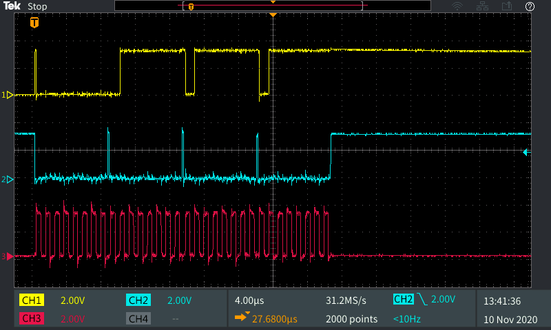
Fig. 265 Data Transmission in config mode, yellow: MISO, blue: FSYNC, red: CLK#
Digital Hall#
Digital inputs provide connectivity for hall sensors. The inputs are called Hallx and QEPx but work identically. In standard configuration the interface works with differential signal pairs. In the first stage a differential to single ended converter provides a logic level signal with 5V level. A level shifter then sets the signals to 3.3V levels.
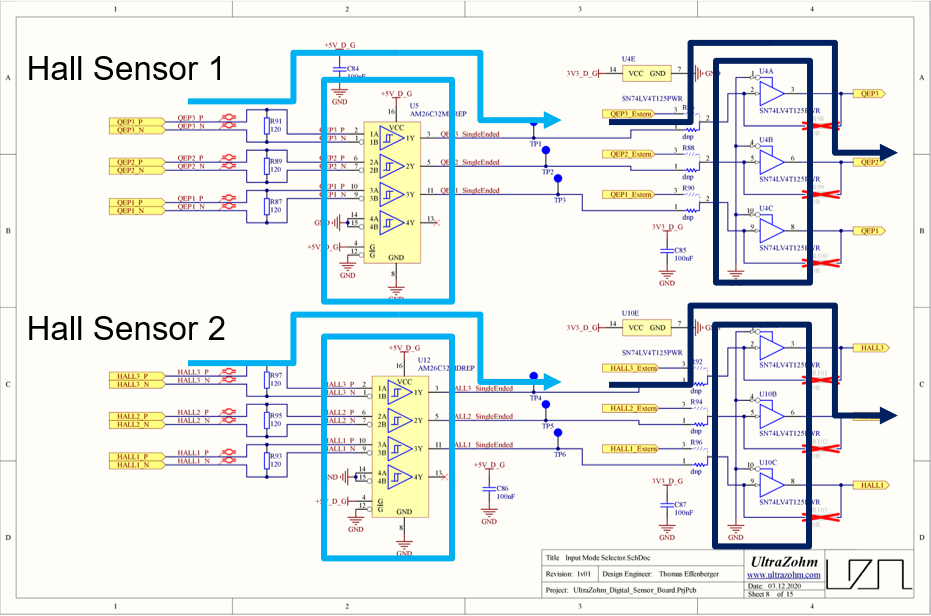
In case the signals are single ended the differential to single ended converter can be bypassed with jumper resistors. If the logic level of those signals is 3.3V already the level shifter can be bypassed as well.
Absolute Encoder#
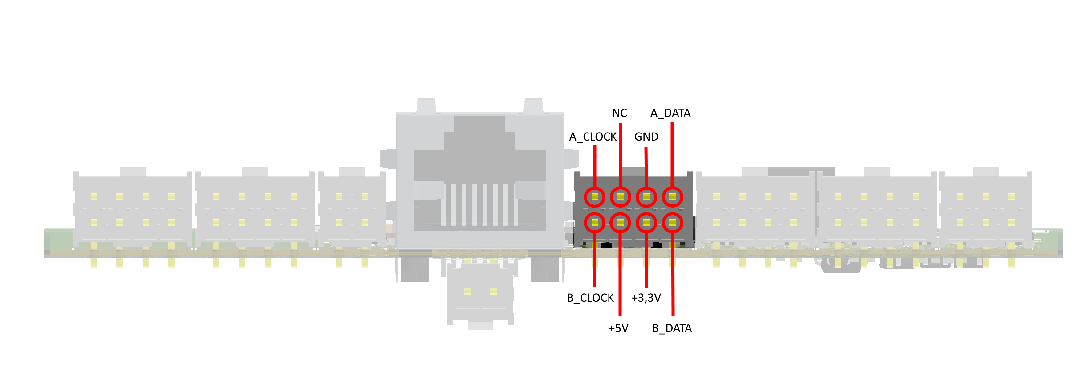
Fully integrated absolute encoders with industrial standard interfaces like SSI can be connected to the absolute encoder interface of the board. On Hardware level this board provides two RS485 transceivers. Their direction is controlled by specific control lines and they can be used either as serial data, serial clock or other functions, depending on the encoder interface. The 5V level control and data lines to the transceivers are routed to a level shifter and then to the I/O connector.
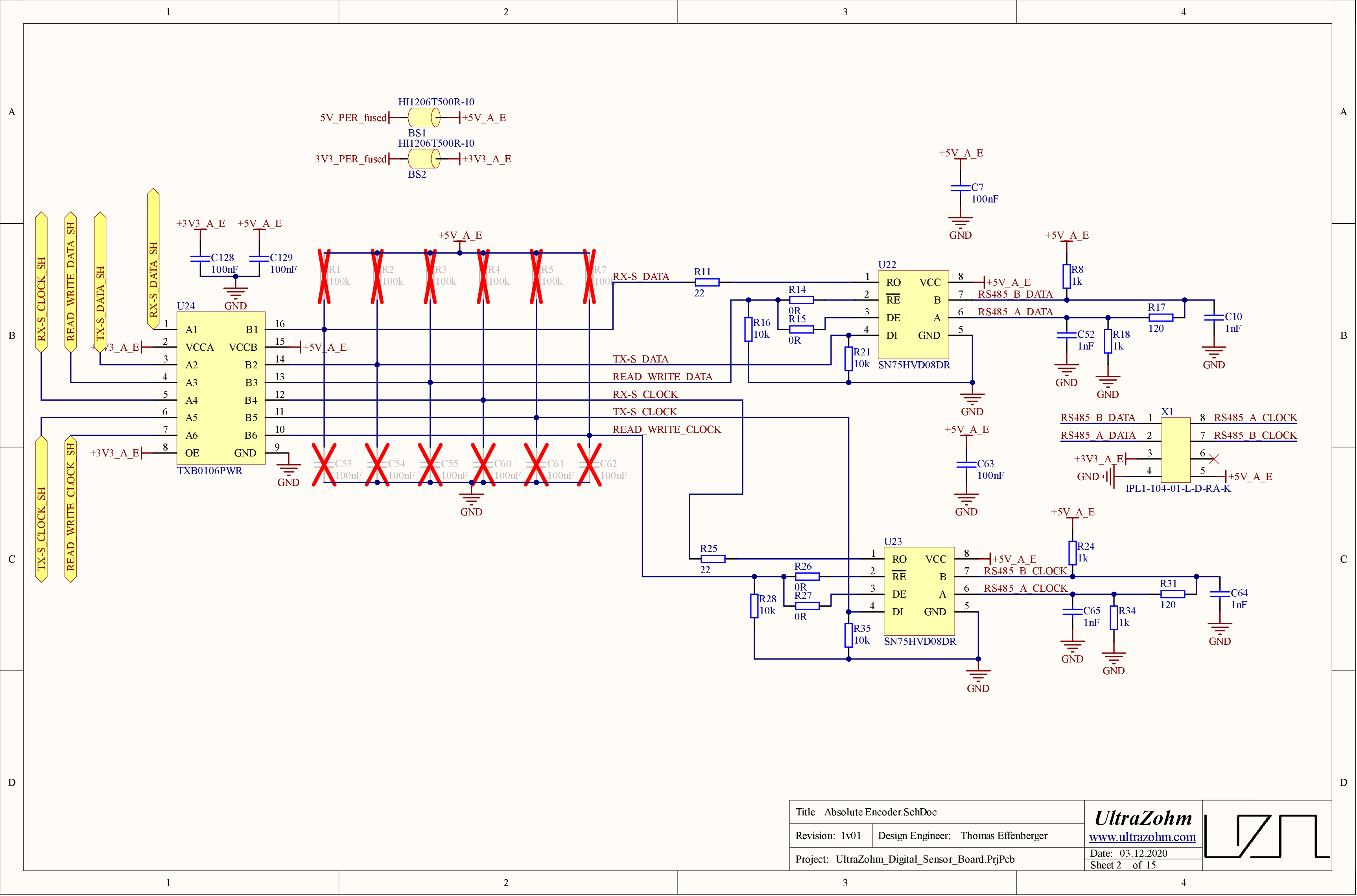
Placement options provide usage with different interface specifications.
Analog Hall#
The analog hall interface is based on the UltraZohm analog board. It is equipped with four independent channels. Each ADC has a serial interface for reading data.
References#
Designed by#
Thomas Effenberger (TUM) in 12/2020