Temperature Card Rev02#
Detailed Description#
Extends the UltraZohm with a temperature measurement ability. This digital adapter card is based on the LTC2983 temperature measurement system. With the ability to measure different sensor types and built-in data preparation, this card extends the functionality of the UltraZohm. The total amount of 60-Channels (40 on the frontpanel, 20 internal) could be wired directly on the card or in the plug for different kind of sensors.
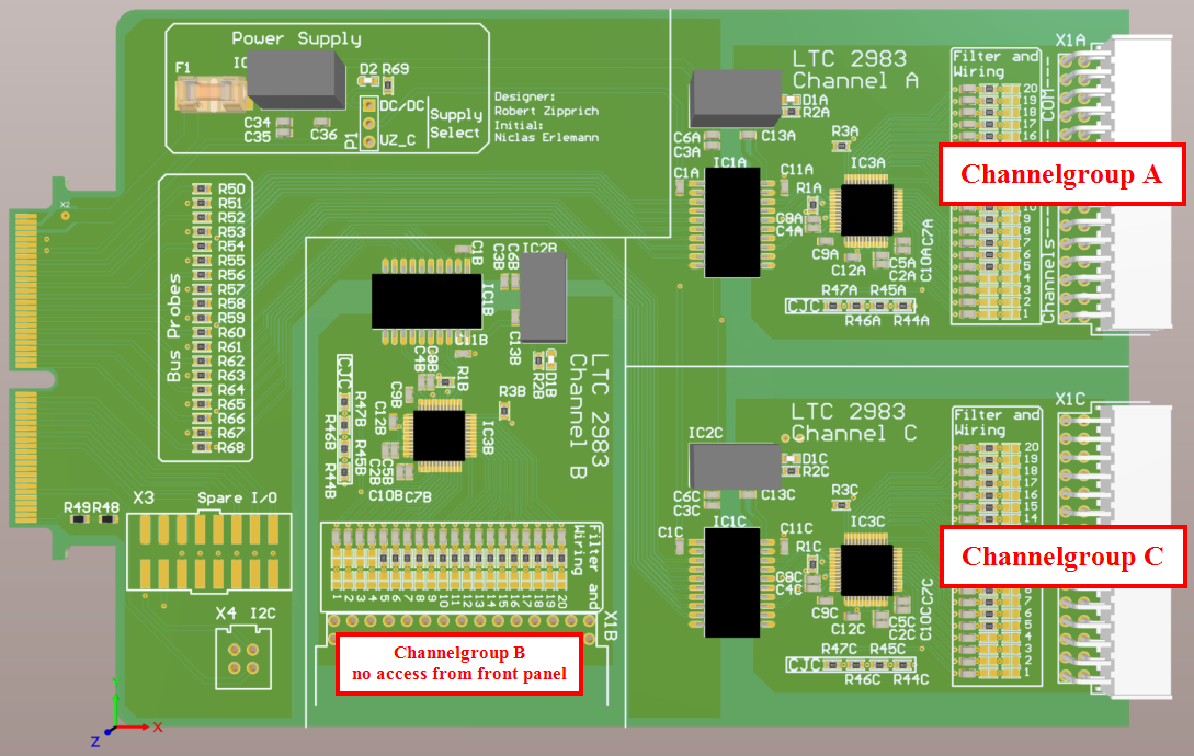
Fig. 271 uz_d_temperature adapter board#
Functionality#
Based on the LTC2983:
Directly Digitize RTDs, Thermocouples, Thermistors, and Diodes
Results Reported in °C or °F
20 Flexible Inputs Allow Interchanging Sensors
Automatic Thermocouple Cold Junction Compensation
Built-In Standard and User-Programmable Coefficients for Thermocouples, RTDs and Thermistors
Configurable 2-, 3- or 4-Wire RTD Configurations
Measures Negative Thermocouple Voltages
Automatic Burn Out, Short-Circuit and Fault Detection
Simultaneous 50Hz/60Hz Rejection
Includes 10ppm/°C (max) Reference (I-Grade)
3 Galvanic isolated LTC2983 available (2 reachable directly on the Front, 1 could be reached with riser-cable)
built-in RC-lowpass filter for each channel
on-board-wiring for easy channel/sensor configuration
Before first use#
Determine correct placement options for correct function
Program CPLDs with the firmware needed for the temperature card uz_d_temperature_ltc2983, see Programming the CPLD for details
Compatibility#
The version of this card is compatible with slots D1-D4. D5 could be used with an own CPLD-file that is not provided right now.
Channelgroup Connector and Pinout#
The pinout is identical for each channelgroup A-C on the temperature card. For connecting sensors to the connector, pre-assembled cables are
a good starting point. Use Samtec MMSD-15-xxx-x-xx.xx-D-P-LDX cables or for assembly of own cables the Samtec IPD1-15-D-K with crimps Samtec CC79L (proper tools required).
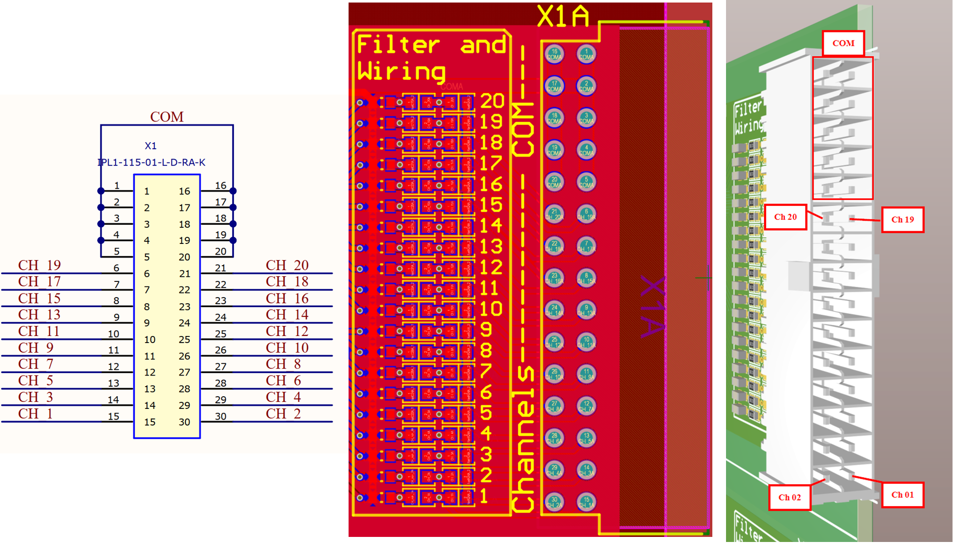
Fig. 272 Channelgroup Pinout#
Implementation with Temperature_Card_Interface IP Core#
The following describes the connecting of the adapter board with the respective IP core at the example of digital adapter slot
D4.For further details on the IP core, see Temperature Card IP Core V1.
Note
Step by step guide.Tcl commands.Tcl commands#
cd [ get_property DIRECTORY [current_project] ]
source ../../tcl_scripts/ip_uz_user_temp_ip_core.tcl
Manual steps:
delete all input/output ports that refer to
D4create proper input/output ports, e.g.
Dig_03_Ch4etc.connect the ports with the proper signals at the
userhierarchydo all the steps for building a bitstream and export it
Step by step guide#
In general, one has to add the Temperature_Card_Interface IP core e.g. to the user hierarchy in the block design of the Vivado project.
This is achieved by right click and Add IP... and typing in the name of the IP core in the search field.
Furthermore, one has to create pins inside the user hierarchy for later connecting them to the proper ports of the adapter board slots, outside of the user hierarchy.
Creating pins is achieved by right click and Create Pin..., defining proper names and direction.
The figure below shows how the result should look like with the IP core placed and all necessary pins created.
The not connected pins are for development and debugging purpose only.
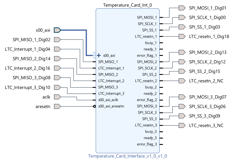
Fig. 273 Pinout within the user hierarchy#
Outside the user hierarchy it then depends on the physical adapter board slot that you are using for the adapter board. Here it is shown at the example of adapter board
slot D4. Create ports by right click and Create Ports... and name the ports according to the figure below, where _Ch4 refers to adapter board slot D4. Pay attention
that no other pins regarding _Ch4 are present in the block design. Delete them to avoid errors during the build or damage to the hardware. Since all three channelgroups share the common
reset signal LTC_resetn_1, all other reset signals are left unconnected.
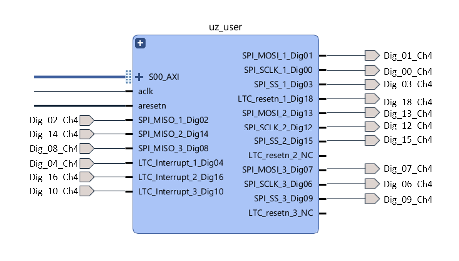
Fig. 274 Pinout and ports outside the user hierarchy#
The mapping between the names and physical pins at the hardware is managed by constraint files. Two types of constraint files are already prepared. They can be found in the sources section
of the Vivado project, as shown below. By default the constraint file for D4 is written in a vectorized (packed) manner that is not proper for accessing single pins. But there are also
constraint files provided that allow access to the single pins. Right click on Digital_D4_packed.xdc and Disable File. Then right click on Digital_AdapterBoard_D4.xdc and
Enable File. By double-clicking (opening) the recently enabled file you will recognize the port names you assigned in the block design and the correct mapping between the IP core
and the adapter board slot is ensured.
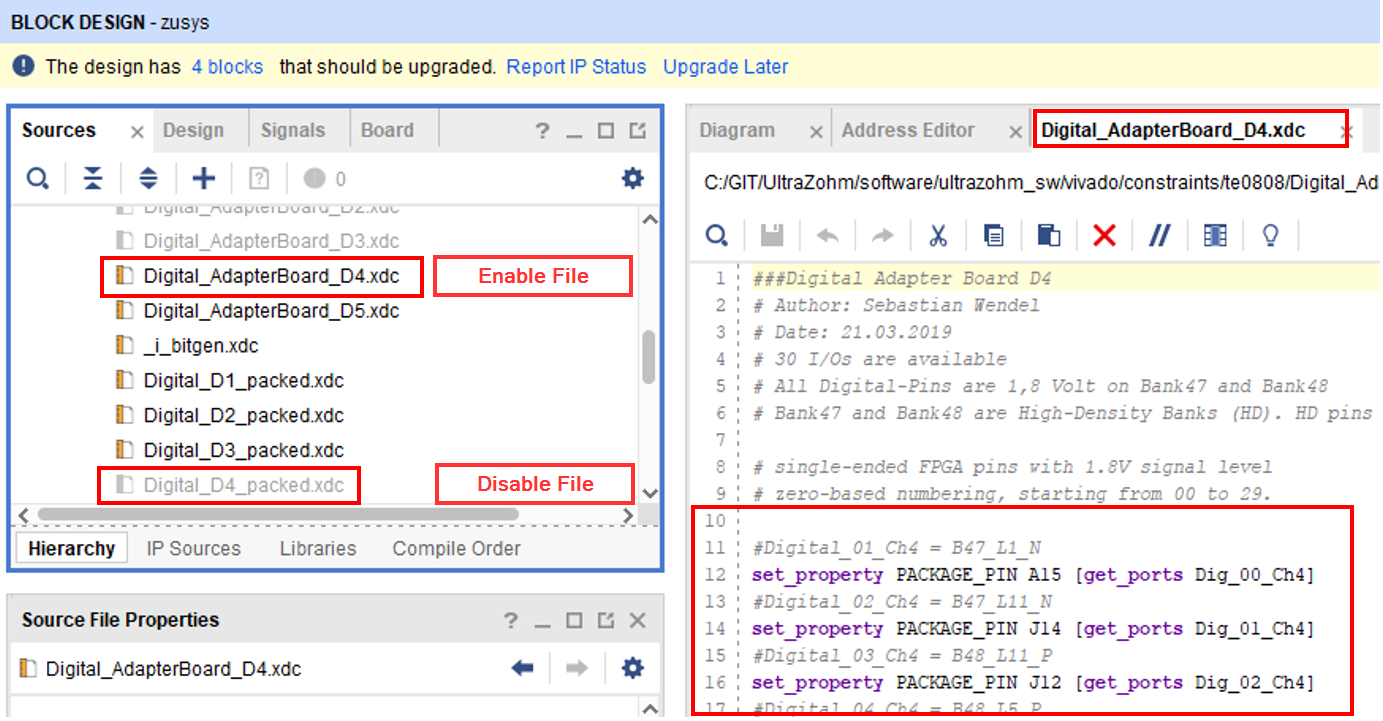
Fig. 275 Constraint file for D4#
Finally do not forget to connect IP core clock (100 MHz), reset signals and AXI interfaces, as well as assigning an AXI base address to the IP core in the Address Editor.
Build the bitstream, export the .xsa file, build the UltraZohm workspace in Vitis and see the respective IP core driver docs for the software part.
Customize Wiring#
Since there exists many possible configurations for the temperature card, its possible to manage some wiring directly on the PCB. For special applications that are not covered by provided assembly variants and the docs, carefully see the datasheet of the LTC2983.
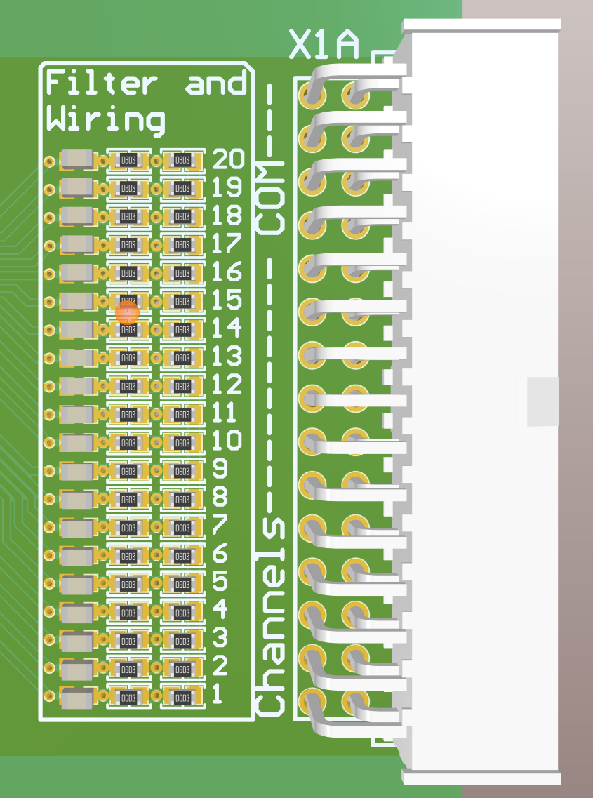
Fig. 276 Filter and Wiring area of one channelgroup for customizing the wiring#
This area is dedicated to implement RC-lowpass filter (C left, R middle) for use with thermocouples or the placement of the Rsense needed for RTD’s.
Further it is possible to enable Rsense-Sharing with 0R-Resistor or solder bridges (R right).
For some use-cases PT100 measurements or Type K Thermocouple, dedicated assembly variants of the PCB exist in the repository, where the user does not
need to reconfigure or resolder the wiring in this section.
References#
Known issues#
Wrong naming convention on the PCB for the channelgroups:
Channel Aon the PCB actually meansChannelGroup AThe assembly variant
All_Thermocouplehas some lacking parts and some should be removed. REMOVE:R55,R61andR67.R44(A-C) toR47(A-C). ADD: AtP1connect theDC/DClabeled pin and the middle pin for power supply. Add0 Ohmresistors at Channels1to4in theFilter and Wiringsection of each channelgroup.Those issues are solved in Rev03 and beyond.
Designed by#
Robert Zipprich (Universität Kassel / EMA) // Michael Hoerner (TH Nürnberg) in 01/2023