Space vector limitation#
-
uz_3ph_dq_t uz_CurrentControl_SpaceVector_Limitation(uz_3ph_dq_t v_input_Volts, float V_dc_volts, float max_modulation_index, float omega_el_rad_per_sec, uz_3ph_dq_t i_ref_Ampere, bool *ext_clamping)#
function to limit reference voltages from a control algorithm of a 3ph-machine.
- Parameters:
v_input_Volts – uz_3ph_dq_t struct with the voltages, which shall be limited
V_dc_volts – DC-link voltage
max_modulation_index – Max possible modulation index for the chosen modulation method. I.e. 1/sqrt(3) for Space-Vector-Modulation. Must be greater than 0.0f
omega_el_rad_per_sec – electrical rotational speed in rad/s
i_ref_Ampere – uz_3ph_dq_t struct for reference dq-currents in Ampere
ext_clamping – flag which states, if the SVL is active
- Returns:
uz_3ph_dq_t
-
uz_6ph_dq_t uz_6ph_Space_Vector_Limitation(uz_6ph_dq_t v_input_Volts, float V_dc_volts, float max_modulation_index, float omega_el_rad_per_sec, uz_6ph_dq_t i_ref_Ampere, bool *ext_clamping)#
function to limit the voltages of a 6ph PMSM. Only applicable if the XY subspace is transformed with -theta_el and the 6ph-PMSM is in the 2N-configuration (separated neutral points).
- Parameters:
v_input_Volts – uz_6ph_dq_t struct with the voltages, which shall be limited
V_dc_volts – DC-link voltage
max_modulation_index – Max possible modulation index for the chosen modulation method. I.e. 1/sqrt(3) for Space-Vector-Modulation. Must be greater than 0.0f
omega_el_rad_per_sec – electrical rotational speed in rad/s
i_ref_Ampere – uz_6ph_dq_t struct for reference dq-currents in Ampere
ext_clamping – flag which states, if the SVL is active
- Returns:
uz_6ph_dq_t struct with limited voltages
Example#
 1#include "uz/uz_CurrentControl/uz_space_vector_limitation.h"
 2int main(void) {
 3   float V_dc_volts = 24.0f;
 4   float omega_el_rad_per_sec = 100.0f;
 5   uz_3ph_dq_t i_reference_Ampere = {.d = 1.0f, .q = 2.0f, .zero = 0.0f};
 6   uz_3ph_dq_t v_input_Volts = {.d = 5.0f, .q = 8.0f, .zero = 0.0f};
 7   bool ext_clamping = false;
 8   float max_modulation_index = 1.0f / sqrtf(3.0f);
 9   uz_3ph_dq_t output = uz_CurrentControl_SpaceVector_Limitation(v_input_Volts, V_dc_volts, max_modulation_index, omega_el_rad_per_sec, i_reference_Ampere, &ext_clamping);
10}
 1#include "uz/uz_CurrentControl/uz_space_vector_limitation.h"
 2int main(void) {
 3   float V_dc_volts = 24.0f;
 4   float omega_el_rad_per_sec = 100.0f;
 5   uz_6ph_dq_t i_reference_Ampere = {.d = 1.0f, .q = 2.0f, .x = 3.0f, y = 4.0f};
 6   uz_6ph_dq_t v_input_Volts = {.d = 5.0f, .q = 8.0f, .x = 10.0f, .y = 3.0f};
 7   bool ext_clamping = false;
 8   float max_modulation_index = 1.0f / sqrtf(3.0f);
 9   uz_6ph_dq_t output = uz_6ph_Space_Vector_Limitation(v_input_Volts, V_dc_volts, max_modulation_index, omega_el_rad_per_sec, i_reference_Ampere, &ext_clamping);
10}
Description#
Limitation for dq-axis#
Limits the input voltages according to the following flowchart. Further information can be found in [1] . This function is already included in the CurrentControl. With the max modulation index \(m_\mathrm{max}\) the following voltages can be calculated.

Fig. 327 space vector limitation flow chart for dq-axis
Limitation for six phases#
Limits the input voltages according to the following scheme.
Note
This only applies for a six-phase machine, where the \(\alpha\beta\)-system is transformed with \(\vartheta_{el}\) into the \(dq\) system and the \(XY\)-system is transformed with \(-\vartheta_{el}\) into the \(xy\)-system. The basis for the \(\alpha\beta\)- and \(XY\)-systems is the Coordinate Transformation. Furthermore, this approach is only valid, if the two neutral points of the 6ph-PMSM are disconnected from each other (2N-configuration).
With the max modulation index \(m_\mathrm{max}\), the maximum stator voltage according to
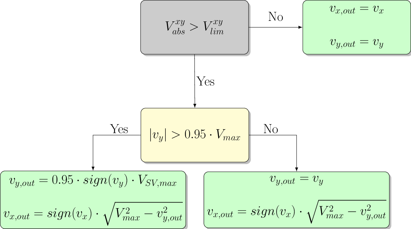
can be realized. First, the \(xy\)-subspace is limited to a maximum voltage of
The absolute value of the \(xy\)-voltages is

Fig. 328 space vector limitation flow chart for xy-axis
Afterwards, the \(dq\)-voltages are limited with the resulting voltages \(v_{x,out}\) and \(v_{y,out}\) of the \(xy\)-limitation according to
with
being the limited voltages of the \(xy\)-axis which will be output.
The voltages of the \(dq\)-subspace are limited according to the flowchart in Fig. 327, with \(V_\mathrm{max}\) being replaced by \(V_\mathrm{lim}^{dq}\).
Sources#
Designed by#
The Limitation for six phases was designed by Dennis Hufnagel.