Digital Optical
Source
Soldering instructions
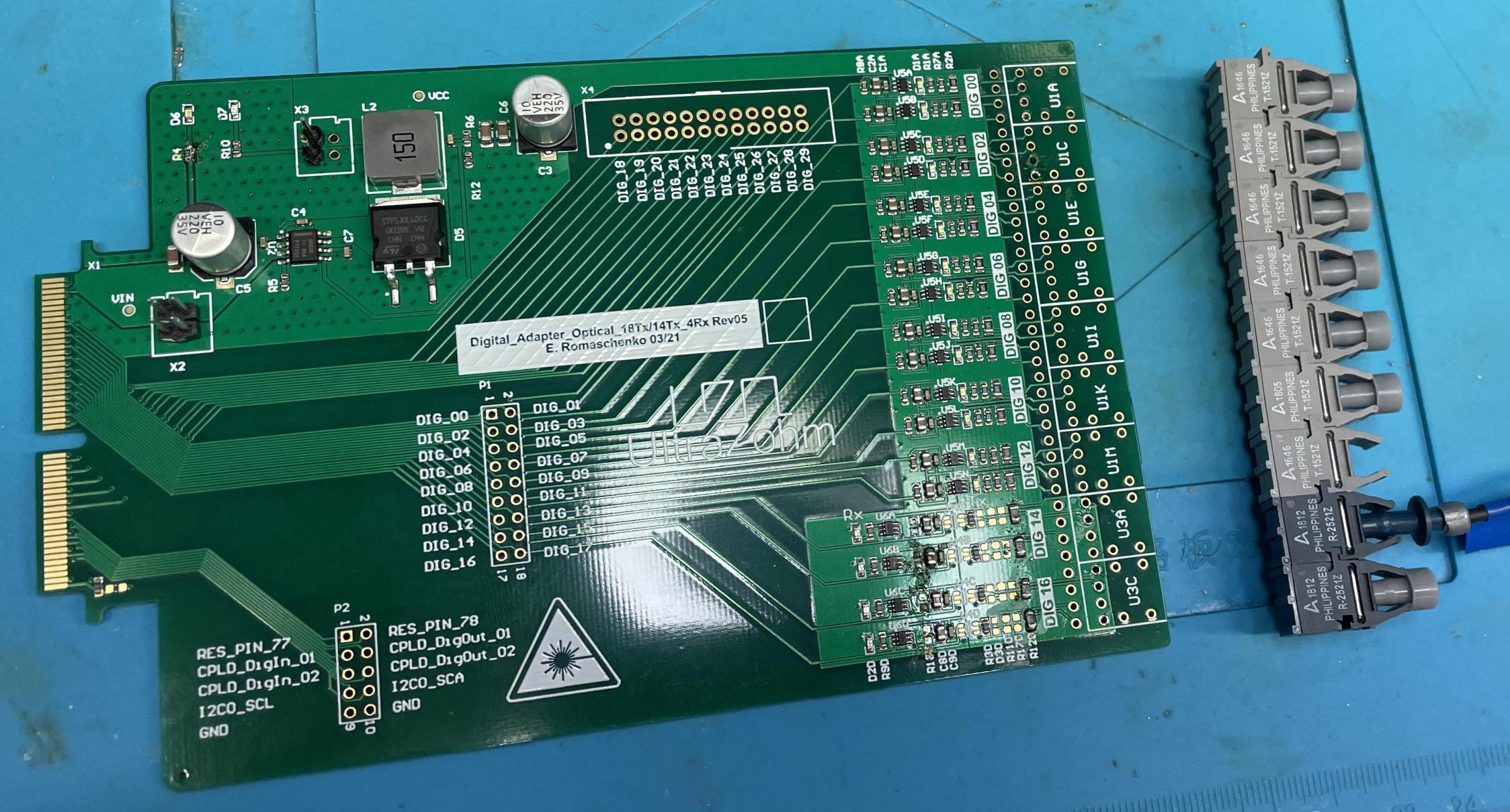
In the following, it is explained how to solder in up to 18
transmitters (Tx) Broadcom HFBR-1521Z or
receivers (Rx) Broadcom HFBR-2521Z.
In this example, 14Tx und 4Rx are soldered in.
Click the optical transmitter and receiver together before soldering them
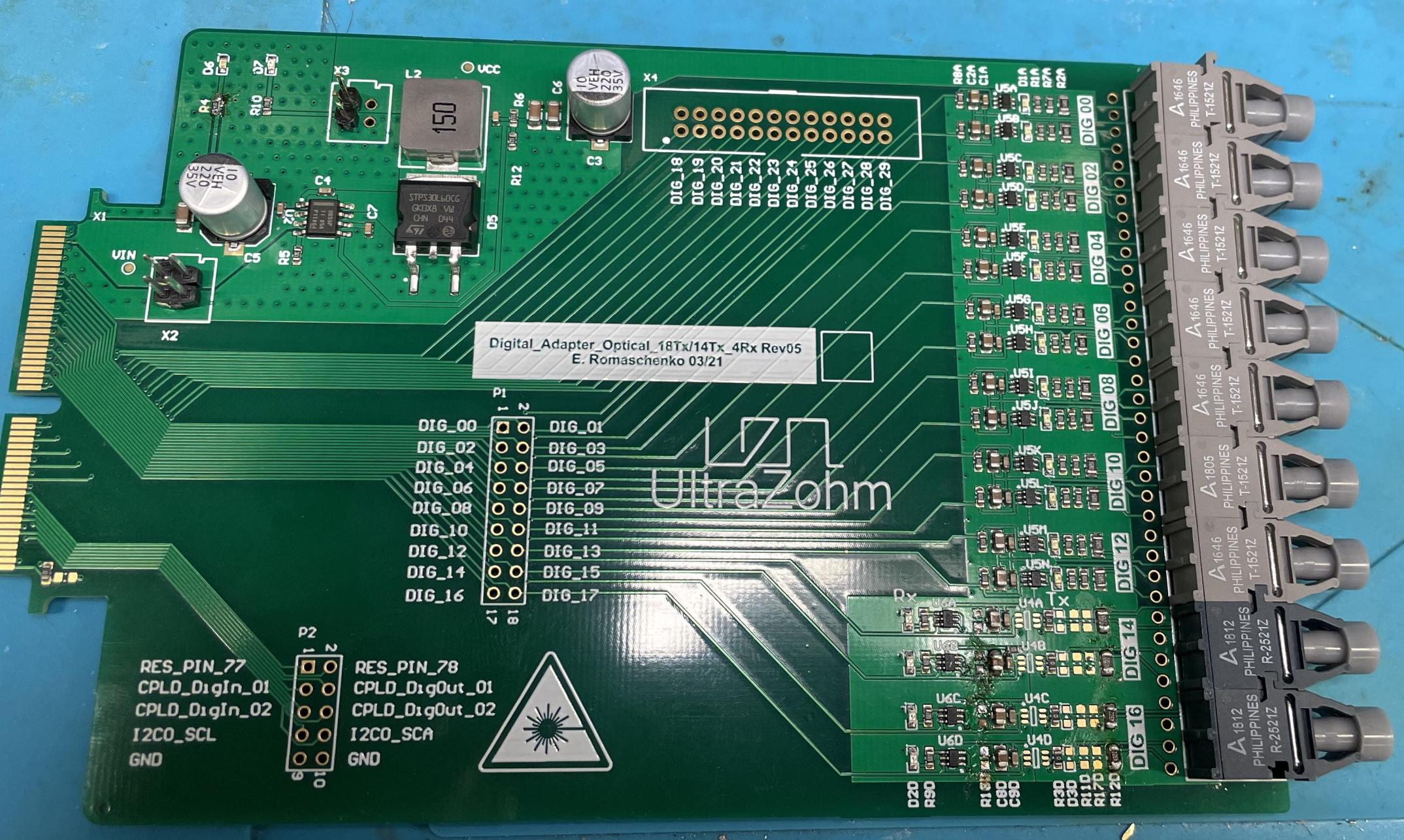
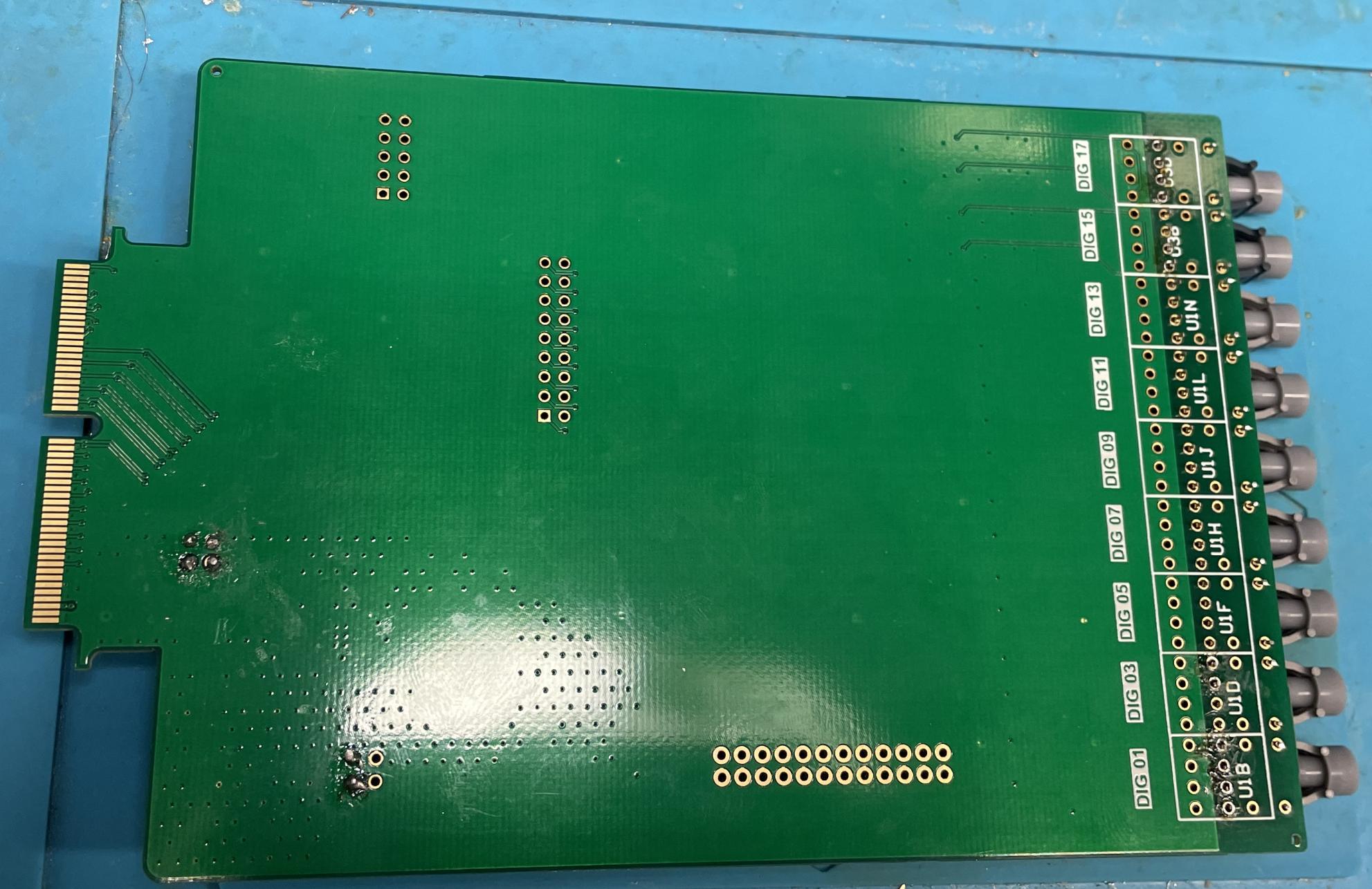
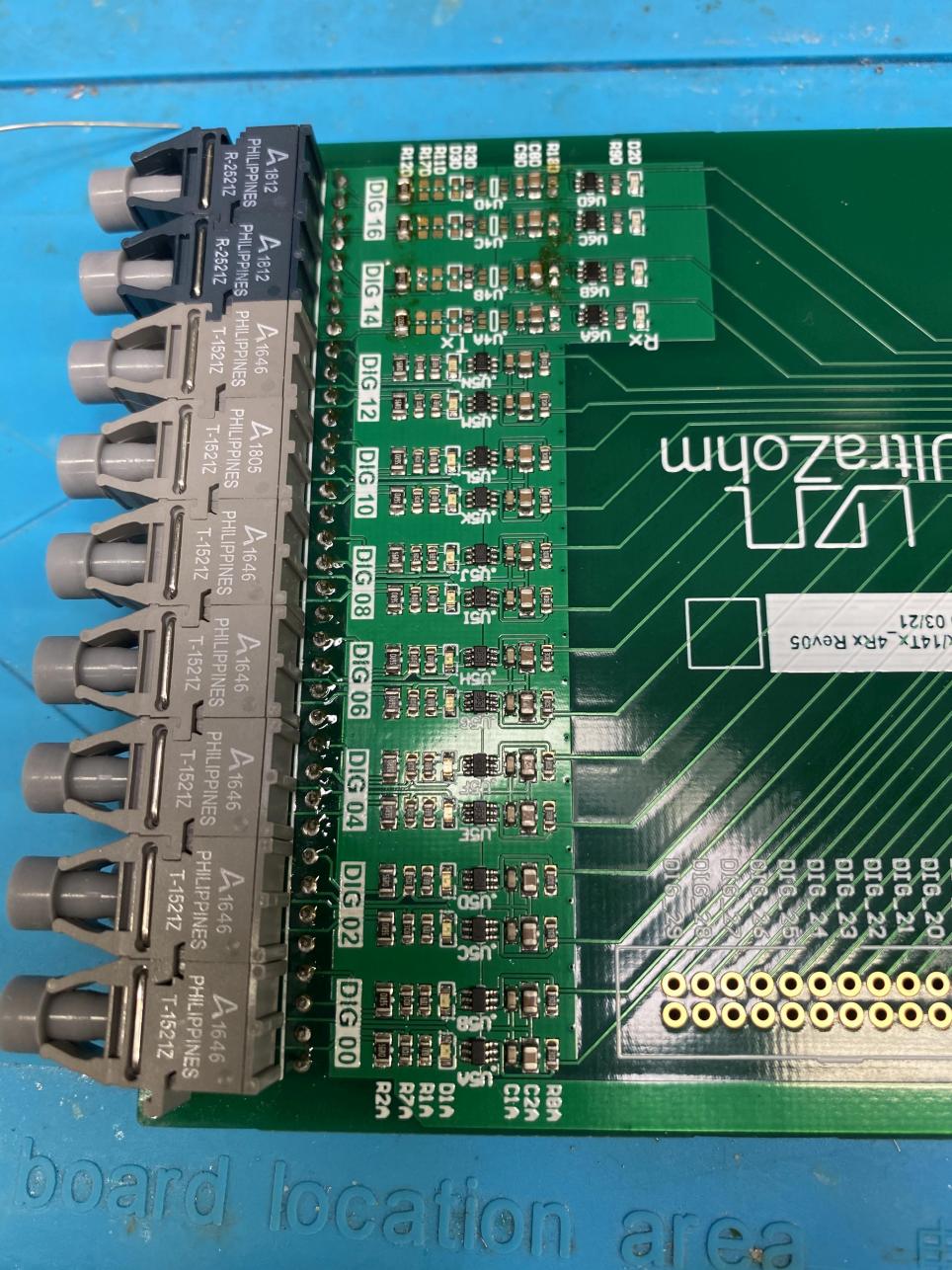
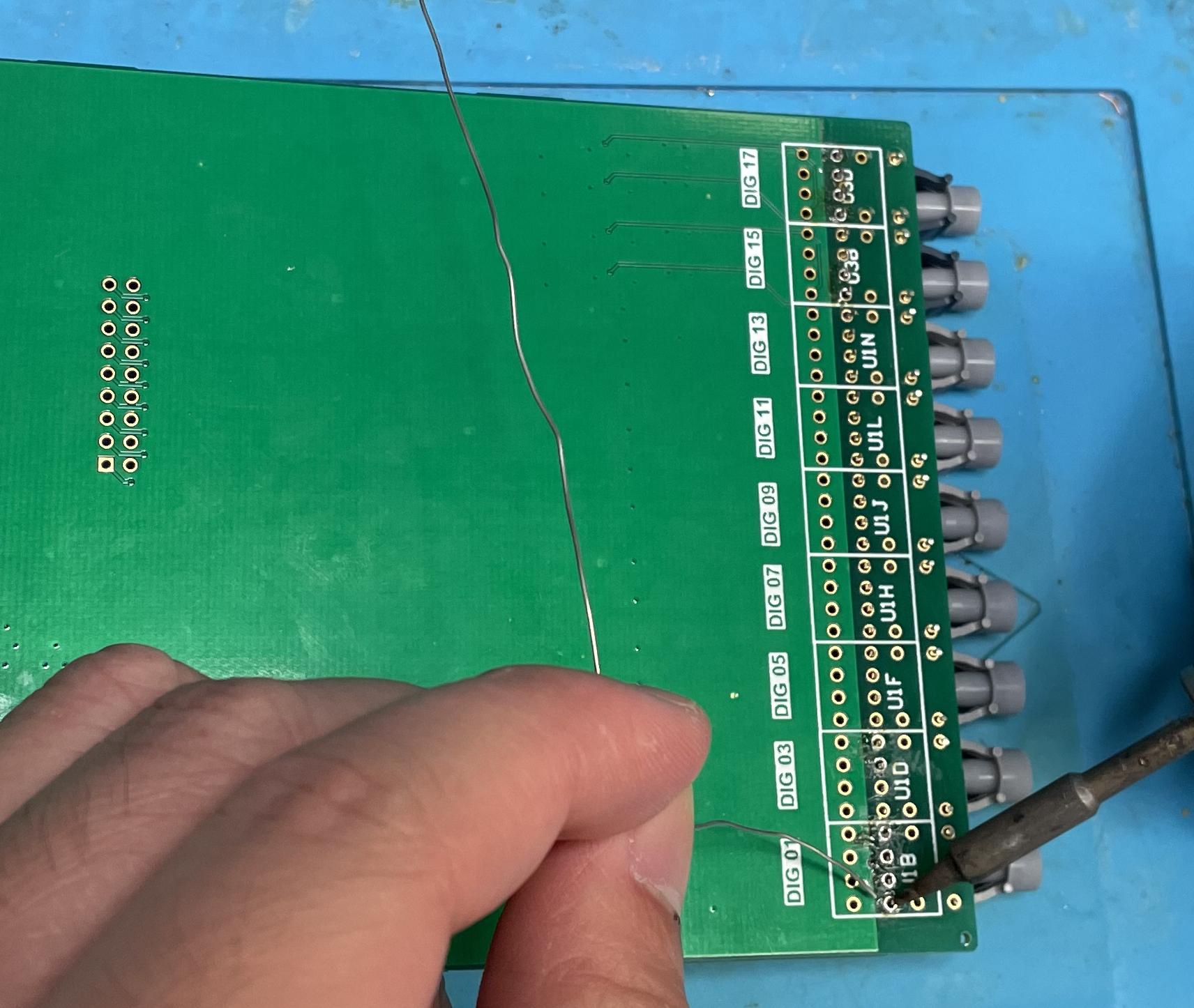
Solder the transmitter/receivers on the top side of the PCB first
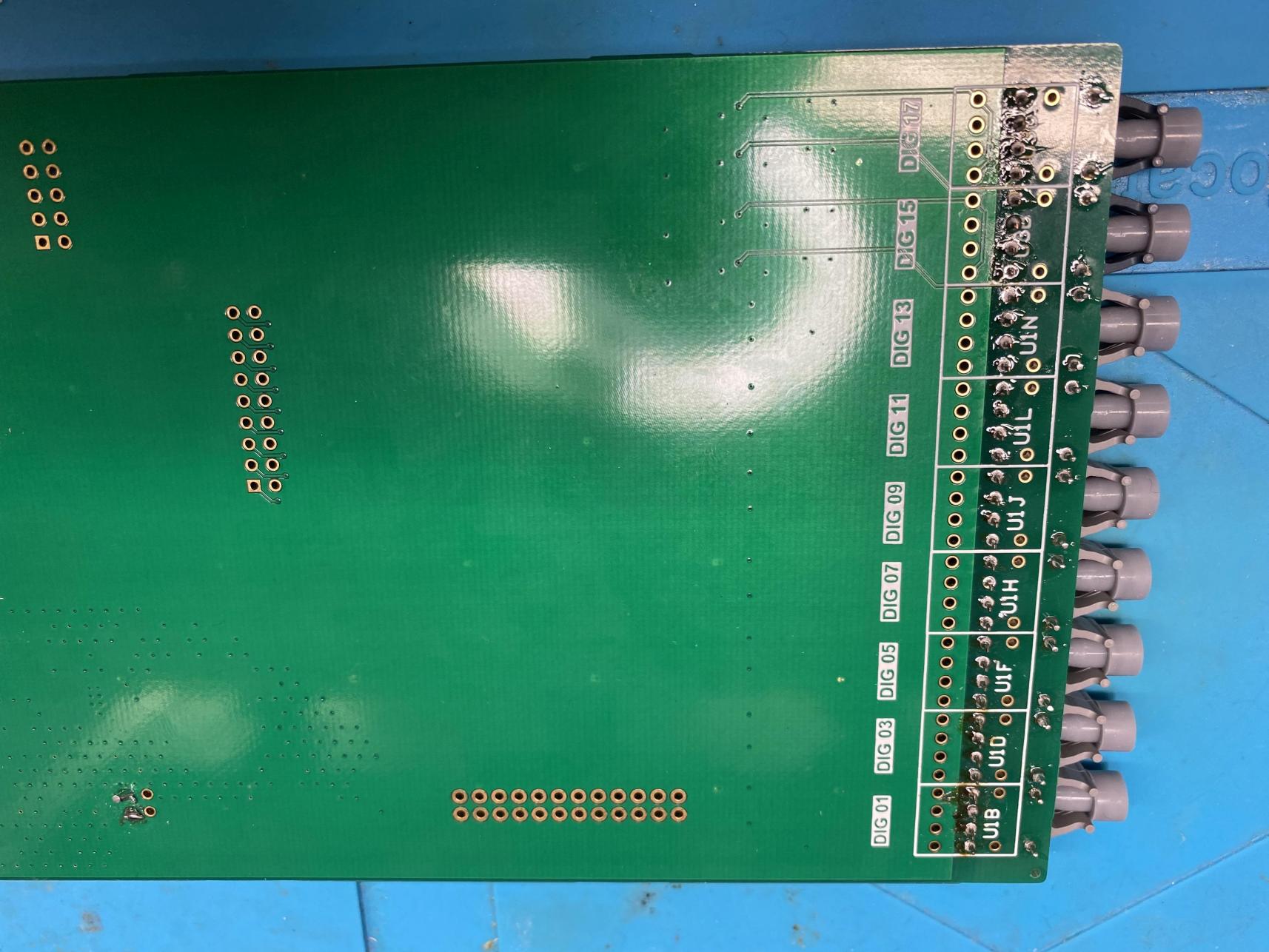
After soldering the top side, shorten all the through-hole pins of the transmitter/receivers that now stick out on the bottom side of the PCB.
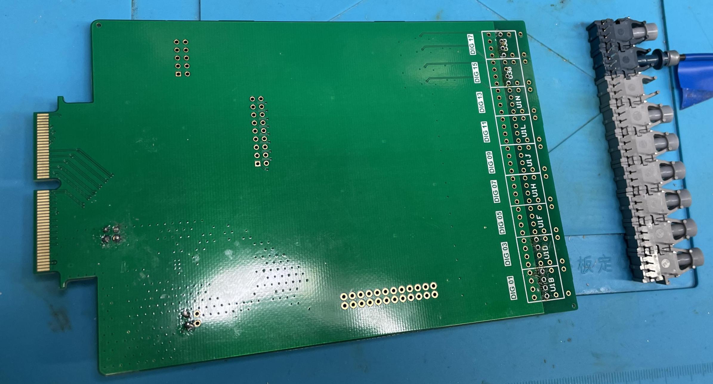
Click together the Rx and Tx for the bottom side, equivalent to step 1
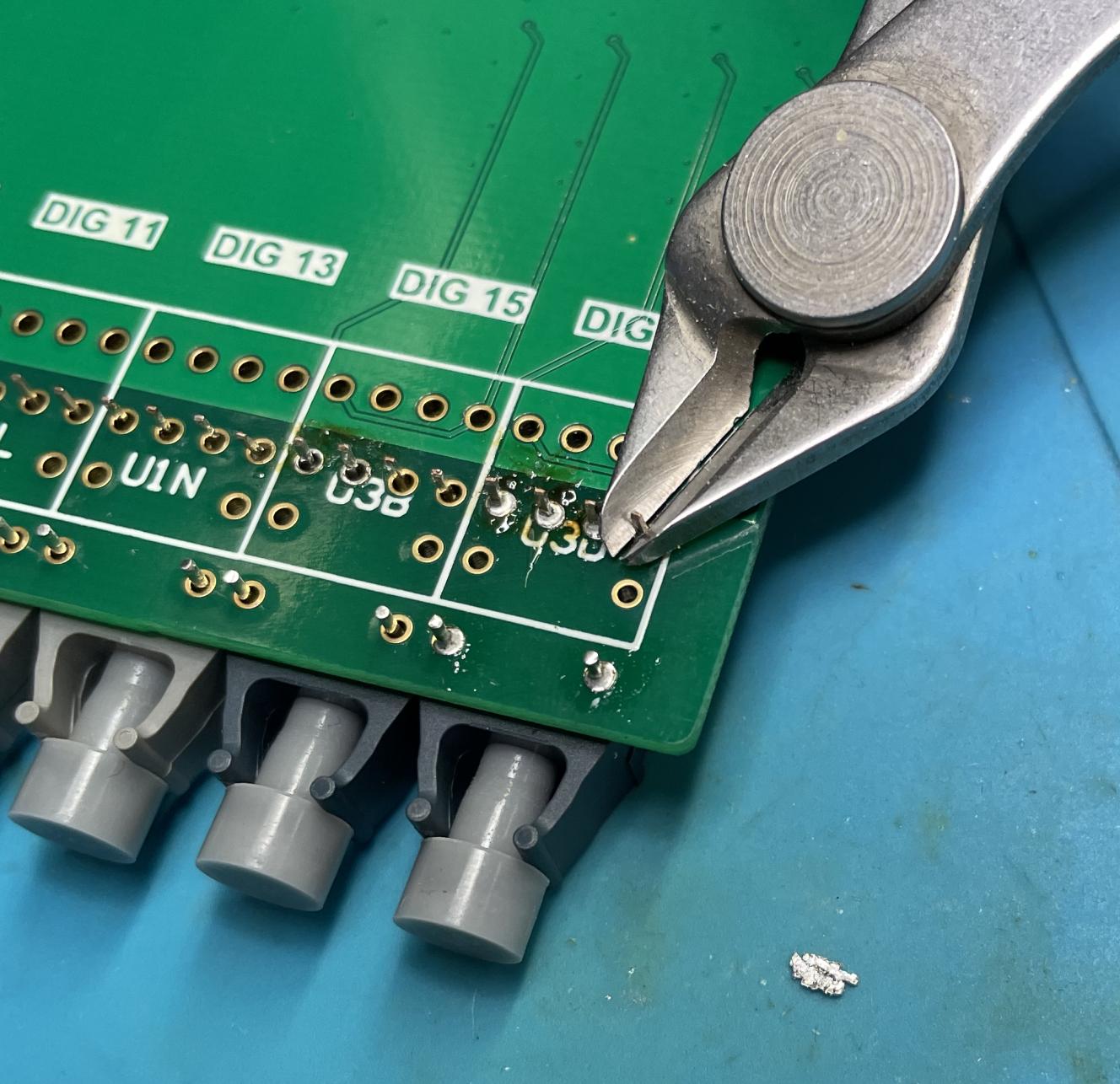
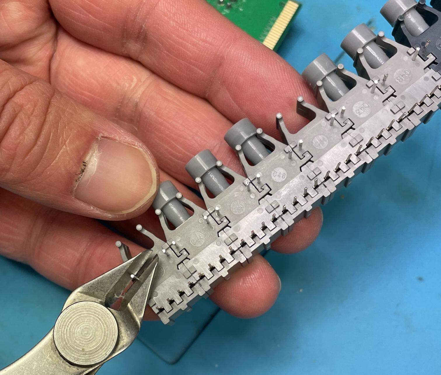
Cut the two pins, that are close to where the cable is plugged in, as short as possible. The referred pin is also cut in the picuture below.
Solder the transmitter/receivers on the bottom side. The shortened through-hole pins (in the schematic pin 5 and 8) are covered by the components on the top side. This is no problem, they do not have to be soldered, since they do not carry any electrical signal.