Interface to power electronics#
To control an inverter with the UltraZohm, the power electronics should be controlled directly by the gate signals. In order to get your inverter compatible with the UltraZohm platform, follow the instructions below. The signals of concern include the gate signals, error flags, and current and/or voltage measurements. The following schematic shows the three different types of signals.
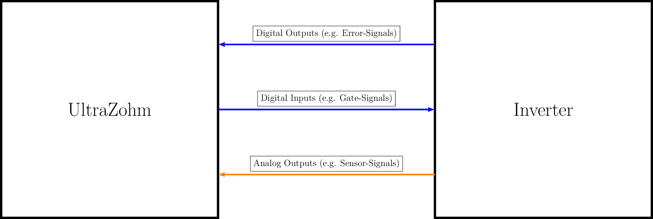
Fig. 230 Signals between UltraZohm and inverter
Digital Signals#
Multiple options are available to handle input or output signals of your inverter:
- Optical signals with optical adapter card (Digital Optical)
Logic HIGH = LED/Transmitter/Receiver ON
Logic LOW = LED/Transmitter/Receiver OFF
- Voltage signals with digital voltage adapter card (Digital Voltage 3U 2v01)
Single-ended signals from inverter to UltraZohm with 3.3 V or 5 V
Single-ended signals from UltraZohm to inverter with 3.3 V, 5 V or 15 V
Differential signals with RS422 transmitter and receiver (Input and Output)
Analog Signals#
For measurement of phase currents and voltages an analog adapter card is available. It is equipped with a 16-bit ADC of +-5 V and an OPV to adjust the incoming signal. To use the basic configuration without setting up the OPV on the adapter card, scale your voltage signals to +-5 V. An overview of possible signal types is listed below. Please refer to the documentation of the latest analog adapter card for more technical details. The adapter card is equipped with two RJ45 sockets. See Analog LTC2311-16 for pinout configuration.
- Voltage signals
Single-ended with offset voltage
Single-ended with ground potential
Differential signal
- Current signals
Using internal shunt resistor on adapter card
Note
Usually an external voltage/current sensor or transducer is needed to add isolation from the high voltage side.