uz_NN_acc#
This IP core implements a configurable MLP network, which was developed using Vitis HLS 2022.2. The implementation and nomenclature follows the principles outlined in uz_nn.
Attention
Variable layer setup of up to 5 hidden layers with ReLU activation function for hidden layers.
Output in the IP core is hard coded to use Linear activation. A different activation function for the output layer is done via software.
The number of neurons in the hidden layers is variable.
Variable number of up to 24 Observations.
Variable number of up to 12 Actions.
Execution time of ~11-12µs for 3x64 setup.
Change of layer or neuron count requires resynthesis of the IP core in Vitis HLS.
Synthesis configuration to prioritize performance or reduce resources.
One default IP core with 3x64 setup is provided.

Features#
Feedforward calculation in floating point
Bias and weights are written to the IP core during initialization
Fully compatible with uz_nn to use IP core as an accelerator
Uses Matrix math as input and outputs
IP core is configured and triggered exclusively by the PS
Blocking and non-blocking operation (see Execution)
Correct size of the observation, weights, bias and action arrays will be asserted
Execution time for a 3x64 setup, with 20 observations and 4 actions takes roughly ~11µs
Unsafe math optimization in Vitis HLS is used
Functionality#
The usage of the IP core driver depends heavily on uz_nn.
First, an instance of the software network has to be initialized, e.g., by loading parameters from a header.
Additionally, an array for the output data of the IP core has to be declared (see Matrix math).
The uz_NN_acc_init function writes the memory addresses of the weight and bias arrays to the IP core.
Subsequently, the IP core reads all the weights & bias data from system memory.
The weights & bias data are only read once during initialization of the IP core.
During runtime, the weights & bias are stored in BRAM and are fixed.
Only the observation and action data are read and written, respectively, during runtime.
Usage#
The following step-by-step description guides the user in order to properly implement the IP core and the respective software driver.
Vivado#
First, the IP core has to be added to the block design in Vivado:
In Vivado, open the project and navigate to
Window->IP-Catalogandright-click->Refresh All Repository.Open the already existing
uz_userhierarchy in the block design.Inside this hierarchy, click on the plus (
+) button to add a new IP core and select one of the following IP cores:Note
Use the
uz_NN_3_64_accIP core for a preconfigured IP core with 3 hidden layers and 64 neurons each.Use customized
uz_NN_X_YYYIP cores for different neuronal network setups. These can be generated using this guide.
Connect the
ap_clkandap_rst_nports as shown in the image below. The IP core is designed for 100 MHz.Add an additional AXI Port on the next reachable
AXI SmartConnectIP core and connect it to thes_axi_controlport of the IP core.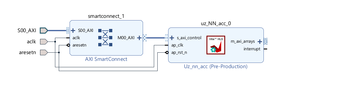
Fig. 496 Block design after steps above#
Double-click on the
zynq_ultra_ps_eblock in the top hierarchy.Navigate to
PS-PL Configuration->PS-PL Interface->Slave Interface.Add a new
AXI HPx FPDInterface and set the Data Width to32. If more than one uz_NN_acc IP core is being implemented, add a corresponding amount ofAXI HPx FPDinterfaces.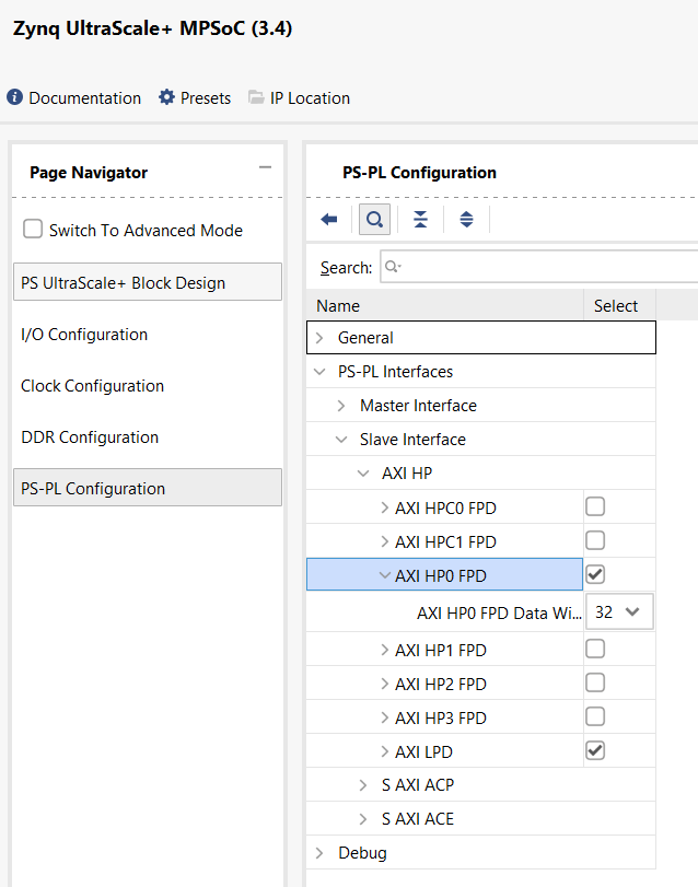
Fig. 497 View of the Zynq configuration#
Press
OK.Connect the
saxihpX_fpd_aclkport to the 100 MHz clock signal.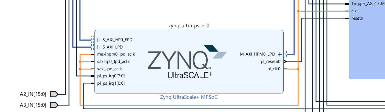
Fig. 498 Zynq clock connection#
Connect the S_AXI_HPX_FPD port to the output
m_axi_arraysport of theuz_NN_accIP core.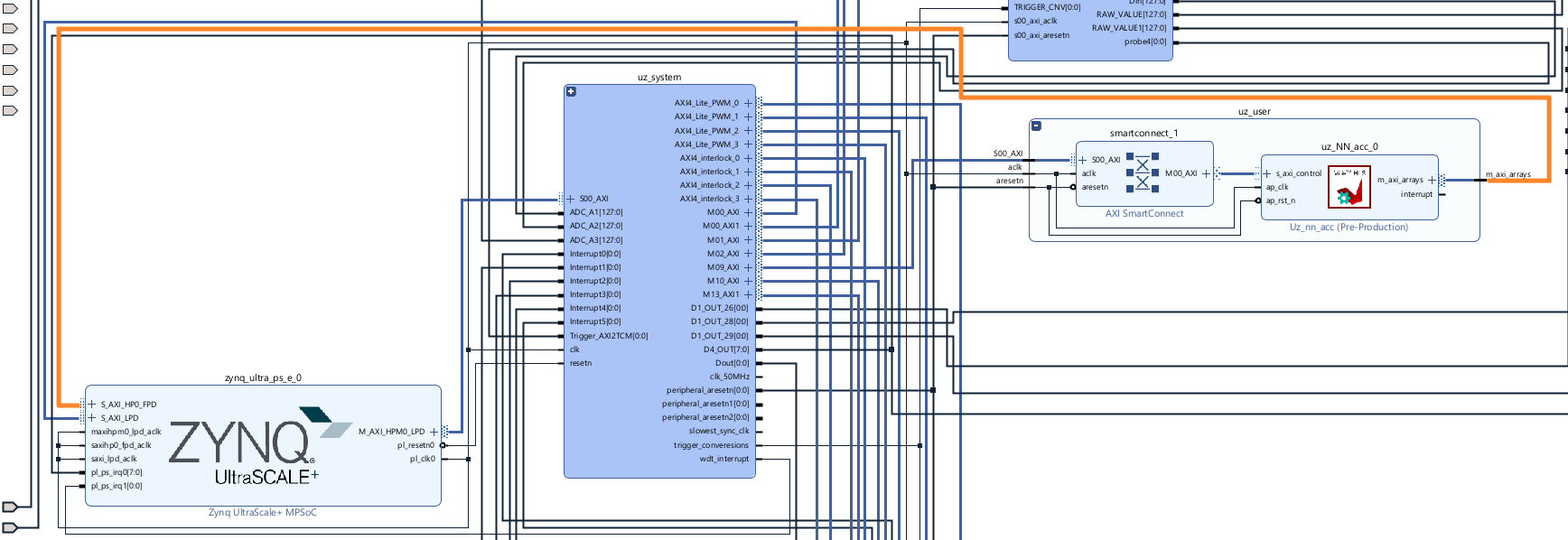
Fig. 499 Zynq axi connection#
Open the
Address Editorand right-click and selectAssign all. This assigns the addresses of the M_axi and S_axi interfaces for the IP core.After assignment, it should look similar to this.
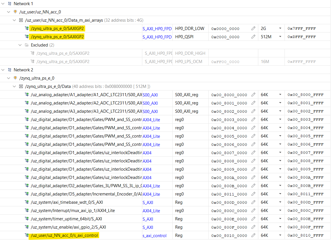
Fig. 500 Address assignment#
Generate the bitstream and export the hardware.
In Vitis, generate the workspace with the exported hardware.
Software#
In the Global configuration, include at least one
uz_NN_accIP core driver instance, one software network instance and(your amount of hidden layers +1)NN_LAYER instance(s).#define UZ_NN_ACC_IP_MAX_INSTANCES 1U #define UZ_NN_LAYER_MAX_INSTANCES 4U #define UZ_NN_MAX_INSTANCES 1U
In the
globalData.hfile, add the following code to theobject_pointers_tstruct:#include "uz/uz_nn/uz_nn.h" #include "uz/uz_matrix/uz_matrix.h" #include "IP_Cores/uz_NN_acc/uz_NN_acc.h" ... typedef struct{ ... uz_matrix_t* matrix_input_acc; uz_matrix_t* matrix_output_acc; uz_nn_t* nn_layer_acc; uz_NN_acc_t* NN_acc_Instance; }object_pointers_t;
Create a header file (e.g.,
init_network_ip_core.h) for theinit_networkfunction:#ifndef INIT_NETWORK_IP_CORE_H #define INIT_NETWORK_IP_CORE_H void init_network(void); #endif /* INIT_NETWORK_IP_CORE_H */
Create an initialization C file (e.g.,
init_network_ip_core.c) for theinit_networkfunction:Warning
Every array and uz_matrix_t object has to be declared with the MEMORY_ALIGN attribute. It aligns the arrays (and therefore its pointers) to 32 byte. Otherwise, undefined behavior regarding the read/write process of the IP core can occur.
#include "../uz/uz_nn/uz_nn.h"
#include "../IP_Cores/uz_NN_acc/uz_NN_acc.h"
#include "../../main.h"
#include "init_network_ip_core.h"
extern DS_Data Global_Data;

#define NUMBER_OF_INPUTS 13U
#define NUMBER_OF_NEURONS_IN_FIRST_LAYER 64U
#define NUMBER_OF_NEURONS_IN_SECOND_LAYER 64U
#define NUMBER_OF_NEURONS_IN_THIRD_LAYER 64U
#define NUMBER_OF_OUTPUTS 4
#define NUMBER_OF_HIDDEN_LAYER 3

float x[NUMBER_OF_INPUTS] MEMORY_ALIGN = {1.0f, 2.0f, 3.0f, 4.0f, 5.0f, 6.0f, 7.0f, 8.0f, 9.0f, 10.0f, 11.0f, 12.0f, 13.0f};
float w_1[NUMBER_OF_INPUTS * NUMBER_OF_NEURONS_IN_FIRST_LAYER] MEMORY_ALIGN = {
#include "layer1_weights.csv"
};
float b_1[NUMBER_OF_NEURONS_IN_FIRST_LAYER] MEMORY_ALIGN = {
#include "layer1_bias.csv"
};
float y_1[NUMBER_OF_NEURONS_IN_FIRST_LAYER] MEMORY_ALIGN = {0};

float w_2[NUMBER_OF_NEURONS_IN_FIRST_LAYER * NUMBER_OF_NEURONS_IN_SECOND_LAYER] MEMORY_ALIGN = {
#include "layer2_weights.csv"
};
float b_2[NUMBER_OF_NEURONS_IN_SECOND_LAYER] MEMORY_ALIGN = {
#include "layer2_bias.csv"
};
float y_2[NUMBER_OF_NEURONS_IN_SECOND_LAYER] MEMORY_ALIGN = {0};

float w_3[NUMBER_OF_NEURONS_IN_FIRST_LAYER * NUMBER_OF_NEURONS_IN_SECOND_LAYER] MEMORY_ALIGN = {
#include "layer3_weights.csv"
};
float b_3[NUMBER_OF_NEURONS_IN_THIRD_LAYER] MEMORY_ALIGN = {
#include "layer3_bias.csv"
};
float y_3[NUMBER_OF_NEURONS_IN_THIRD_LAYER] MEMORY_ALIGN = {0};

float w_4[NUMBER_OF_NEURONS_IN_THIRD_LAYER * NUMBER_OF_OUTPUTS] MEMORY_ALIGN = {
#include "layer4_weights.csv"
};
float b_4[NUMBER_OF_OUTPUTS] MEMORY_ALIGN = {
#include "layer4_bias.csv"
};
float y_4[NUMBER_OF_OUTPUTS] MEMORY_ALIGN = {0};

struct uz_nn_layer_config software_nn_config[4] = {
    [0] = {
        .activation_function = activation_ReLU,
        .number_of_neurons = NUMBER_OF_NEURONS_IN_FIRST_LAYER,
        .number_of_inputs = NUMBER_OF_INPUTS,
        .length_of_weights = UZ_MATRIX_SIZE(w_1),
        .length_of_bias = UZ_MATRIX_SIZE(b_1),
        .length_of_output = UZ_MATRIX_SIZE(y_1),
        .weights = w_1,
        .bias = b_1,
        .output = y_1},
    [1] = {.activation_function = activation_ReLU, .number_of_neurons = NUMBER_OF_NEURONS_IN_SECOND_LAYER, .number_of_inputs = NUMBER_OF_NEURONS_IN_SECOND_LAYER, .length_of_weights = UZ_MATRIX_SIZE(w_2), .length_of_bias = UZ_MATRIX_SIZE(b_2), .length_of_output = UZ_MATRIX_SIZE(y_2), .weights = w_2, .bias = b_2, .output = y_2},
    [2] = {.activation_function = activation_ReLU, .number_of_neurons = NUMBER_OF_NEURONS_IN_THIRD_LAYER, .number_of_inputs = NUMBER_OF_NEURONS_IN_THIRD_LAYER, .length_of_weights = UZ_MATRIX_SIZE(w_3), .length_of_bias = UZ_MATRIX_SIZE(b_3), .length_of_output = UZ_MATRIX_SIZE(y_3), .weights = w_3, .bias = b_3, .output = y_3},
    //Note:Although IP-Core is hardcoded to activation_linear for the output the specified activation function for the last layer will be applied in software
    [3] = {.activation_function = activation_tanh, .number_of_neurons = NUMBER_OF_OUTPUTS, .number_of_inputs = NUMBER_OF_NEURONS_IN_THIRD_LAYER, .length_of_weights = UZ_MATRIX_SIZE(w_4), .length_of_bias = UZ_MATRIX_SIZE(b_4), .length_of_output = UZ_MATRIX_SIZE(y_4), .weights = w_4, .bias = b_4, .output = y_4}};

struct uz_matrix_t input_matrix MEMORY_ALIGN={0};
struct uz_matrix_t output_matrix MEMORY_ALIGN={0};

void init_network(void){
   Global_Data.objects.matrix_input_acc=uz_matrix_init(&input_matrix,x,UZ_MATRIX_SIZE(x),1U,NUMBER_OF_INPUTS);
   Global_Data.objects.matrix_output_acc=uz_matrix_init(&output_matrix,y_4,UZ_MATRIX_SIZE(y_4),1U,NUMBER_OF_OUTPUTS);
   Global_Data.objects.nn_layer_acc = uz_nn_init(software_nn_config, 4U); //Warning is a GCC 11 bug

   struct uz_NN_acc_config_t IP_config = {
                   .software_network = Global_Data.objects.nn_layer_acc,
                   .base_address = XPAR_UZ_USER_UZ_NN_ACC_0_S_AXI_CONTROL_BASEADDR //May needs adjusting
   };
   Global_Data.objects.NN_acc_Instance = uz_NN_acc_init(IP_config, Global_Data.objects.matrix_input_acc, Global_Data.objects.matrix_output_acc);
 }
After including your header file (
init_network_ip_core.h) in themain.h, add the init function to the main.c file:... switch (initialization_chain) { .... case init_ip_cores: ... init_network(); ... initialization_chain = print_msg; break; case print_msg: ....
To use the IP core in the ISR, add the following code to the
isr.c:float Output[4] = {0}; float Observation[13] = {0}; ... void ISR_Control(void *data) { ... Observation[0] = ...; Observation[1] = ...; Observation[2] = ...; Observation[3] = ...; Observation[4] = ...; Observation[5] = ...; Observation[6] = ...; Observation[7] = ...; Observation[8] = ...; Observation[9] = ...; Observation[10] = ...; Observation[11] = ...; Observation[12] = ...; if (current_state==control_state) { for (uint32_t i = 0; i < 13U; i++) { uz_matrix_set_element_zero_based(Global_Data.objects.matrix_input_acc,Observation[i],0U,i); } uz_NN_acc_ff_blocking(Global_Data.objects.NN_acc_Instance); Output[0] = uz_matrix_get_element_zero_based(Global_Data.objects.matrix_output_acc,0U,0U); Output[1] = uz_matrix_get_element_zero_based(Global_Data.objects.matrix_output_acc,0U,1U); Output[2] = uz_matrix_get_element_zero_based(Global_Data.objects.matrix_output_acc,0U,2U); Output[3] = uz_matrix_get_element_zero_based(Global_Data.objects.matrix_output_acc,0U,3U); } ...
float Output[4] = {0};
float Observation[13] = {0};
...
void ISR_Control(void *data)
{
   ...
   Observation[0] = ...;
   Observation[1] = ...;
   Observation[2] = ...;
   Observation[3] = ...;
   Observation[4] = ...;
   Observation[5] = ...;
   Observation[6] = ...;
   Observation[7] = ...;
   Observation[8] = ...;
   Observation[9] = ...;
   Observation[10] = ...;
   Observation[11] = ...;
   Observation[12] = ...;
   if (current_state==control_state) {
      for (uint32_t i = 0; i < 13U; i++) {
           uz_matrix_set_element_zero_based(Global_Data.objects.matrix_input_acc,Observation[i],0U,i);
      }
      uz_NN_acc_ff_non_blocking(Global_Data.objects.NN_acc_Instance);
      //do something else here
      uz_NN_acc_get_result_blocking(Global_Data.objects.NN_acc_Instance);
      Output[0] = uz_matrix_get_element_zero_based(Global_Data.objects.matrix_output_acc,0U,0U);
      Output[1] = uz_matrix_get_element_zero_based(Global_Data.objects.matrix_output_acc,0U,1U);
      Output[2] = uz_matrix_get_element_zero_based(Global_Data.objects.matrix_output_acc,0U,2U);
      Output[3] = uz_matrix_get_element_zero_based(Global_Data.objects.matrix_output_acc,0U,3U);
   }
   ...
Execution#
The regular calculation with the IP core using the software driver and writing the inputs and waiting for the output is a blocking operation. The driver triggers the calculation and waits until it is finished. The processor can not do any other tasks.
uz_NN_acc_ff_blocking(instance);        // Triggering & Calculation takes 12us (example)
uz_sleep_useconds(10);                  // Takes 10us
                                        // Takes 22us total
        sequenceDiagram
    participant Processor
    participant Driver
    Processor->>Driver: uz_NN_acc_ff_blocking
    Driver->>IP-Core: Flush cache for input
    Driver->>IP-Core: Trigger calculation
    loop
        Driver->>IP-Core: Read valid output
        Driver->>Driver: Valid output true?
    end
    Driver->>Processor: Invalidate cache for output
An alternative to the blocking calculation is a concurrent approach. In this, the IP core calculation is triggered, the processor is free to do other tasks, and the data are fetched after the calculation is finished. This way, the calculation between trigger and retrieval of result does not add to the total required time if the task in between takes less time than the IP core calculation. Note that this means the actual calculation time of network without the communication overhead of the read/write operations.
uz_NN_acc_ff_non_blocking(instance);        // Triggering takes 2us
uz_sleep_useconds(10);                      // Takes 10us //Calculation runs concurrently
uz_NN_acc_get_result_blocking(instance);    // Takes 3us
                                            // Takes 15us total
        sequenceDiagram
    participant Processor
    participant Driver
    Processor->>Driver: uz_NN_acc_ff_non_blocking
    Driver->>IP-Core: Flush cache for input
    Driver->>IP-Core: Trigger calculation
    Processor->>Software: Do something else
    Software->>Processor: return
    Processor->>Driver: uz_NN_acc_get_result_blocking
    Driver->>IP-Core: Trigger writing output
    loop
        Driver->>IP-Core: Read valid output
        Driver->>Driver: Valid output true?
    end
    Driver->>Processor: Invalidate cache for output
Customize IP core#
The IP core can be configured according to your needs (neuron count & layer setup). However, for this to work, the IP core will need to be synthesized again using the new setup. This guide will walk you through the process.
On Windows, make sure that Vitis HLS is added to your path variables.
Navigate to
ip_cores\uz_NN_acc\uz_NNand open theuz_MMult_MaxSize.hfile.Change the user-definable variable to your needs.
Note
A maximum of 5 hidden layers can be configured.
Neurons can be configured on a per-hidden-layer basis as desired. The output layer size is automatically appropriately sized to the last hidden layer (if hidden layers < 5). Note, however, that increasing the neuron count increases the resource usage significantly. Increasing the number of layers is more resource-efficient in terms of FPGA usage.
The
Performance_Targetvariable can be used if the generated IP core resources are too much for your specific FPGA. Whilst 1==best performance, a higher number reduces the resource usage by decreasing performance. A maximum of Performance_Target==Neurons_per_HiddenLayer can be set.Examples of the resource usage for different configurations can be found here.
//User define
#define Hidden_Layers 3 //max 5
#define Neurons_1st_Hidden_Layer 64
#define Neurons_2nd_Hidden_Layer 32
#define Neurons_3rd_Hidden_Layer 96
#define Neurons_4th_Hidden_Layer 32
#define Neurons_5th_Hidden_Layer 64
#define Performance_Target 1
Save the file and navigate to
ip_cores\uz_NN_accNote
Up to 5 custom IP cores can be generated and stored.
To facilitate this, 5 different synthesis solutions are provided.
The name of the IP core can be configured in this solution. This is necessary to avoid clashes in Vivado.
Example for description:
5x128_setupExample for IP core display name:
uz_NN_5_128_accExample for IP core name:
uz_NN_5_128
Configure solution1 by opening the file
uz_NN/solution1/script.tcl.Edit the entry in line 27
-description XxYYY_setup -display_name uz_NN_X_YYY_acc -ipname uz_NN_X_YYY
...
Give the IP core an appropriate name and description. E.g.,
-description 5x128_setup -display_name uz_NN_5_128_acc -ipname uz_NN_5_128.Save the file.
Open the terminal and enter
vitis_hls -f uz_NN/solution1/script.tcl.Vitis HLS will now create the project, synthesis your design, and export the RTL code.
After you see
[HLS 200-111] Finished Command export_design, the synthesis and export are finished.A resource estimation can be found in
uz_NN_acc\uz_NN\solution1\syn\reportundercsynth.rpt. In Vivado, the resource usage (except for DSP Slices) is a bit lower than stated in HLS.[Optional] You can now open the project in the Vitis HLS GUI or with
vitis_hls -p uz_NN.In Vivado, open the project and navigate to
Window->IP-Catalogandright-click->Refresh All Repository.After that, follow the guide to add the IP core to the block design.
[Optional] You can now generate another IP core with a different configuration, by following this guide again. Modify
uz_MMult_MaxSize.hagain and then use solution2-5.
Resource utilization#
The resource utilization depends heavily on the configuration of the IP core. The following table shows the resource usage in Vivado for different configurations. Generally, more hidden layers is more resource efficient than more neurons per layer. Yours may vary slightly.
Setup |
BRAM |
DSP |
FF |
LUT |
LUTRAM |
|---|---|---|---|---|---|
1x32 |
30.5 |
161 |
16k |
15k |
707 |
5x32 |
96.5 |
161 |
22k |
23k |
1081 |
1x64 |
47 |
321 |
27k |
24k |
729 |
3x64 |
112 |
321 |
34k |
32k |
542 |
5x64 |
177 |
321 |
39k |
39k |
1097 |
1x128 |
80 |
641 |
50k |
45k |
783 |
5x128 |
338 |
641 |
72k |
74k |
1469 |
1x256 |
147 |
1281 |
95k |
93k |
658 |
5x256 |
665 |
1281 |
170k |
153k |
848 |
By adjusting the #define Performance_Target 1 to, e.g., 4, the resources for BRAM, LUTs and DSP slices are reduced at the cost of higher latency.
Setup |
BRAM |
DSP |
FF |
LUT |
LUTRAM |
|---|---|---|---|---|---|
5x64 |
48 |
81 |
45k |
32k |
1557 |
5x128 |
89 |
161 |
83k |
59k |
2371 |
5x256 |
302 |
321 |
169k |
122k |
13005 |
Further improvements#
Further improvements are planned for the IP core and in development:
Updating weights & bias during runtime.
Driver reference#
-
typedef struct uz_NN_acc_t uz_NN_acc_t#
Object definition of the IP-Core driver.
-
struct uz_NN_acc_config_t#
-
uz_NN_acc_t *uz_NN_acc_init(struct uz_NN_acc_config_t config, uz_matrix_t const *const observation, uz_matrix_t const *const action)#
Initializes one driver instance of the IP-Core.
- Parameters:
config – configuration struct
observation – Pointer from which the input data is read
action – Pointer to which the output data is written
- Returns:
uz_NN_acc_t*
-
void uz_NN_acc_ff_blocking(uz_NN_acc_t *self)#
Calculates one forward pass of the network and reads out the data. This function is blocking in the sense that data is written to the IP-Core, the is_done output flag is polled, and the output is read. I.e., this function waits for the IP-Core to finish the calculation.
- Parameters:
self – Pointer to IP-Core driver instance
-
void uz_NN_acc_ff_non_blocking(uz_NN_acc_t *self)#
Triggers the calculation of one forward pass of the network. This function is not blocking and returns after the calculation is started. This enables the concurrent execution of code on the processor while the IP-Core calculates the result of the network.
- Parameters:
self – Pointer to IP-Core driver instance
-
void uz_NN_acc_get_result_blocking(uz_NN_acc_t *self)#
Returns the calculation result of the last forward pass of the network. User has to take care to trigger the calculation before getting the results. The function is blocking, i.e., the is_done output flag of the IP-Core is polled. Intended to use with uz_NN_acc_ff_non_blocking to allow concurrent calculations on PS and PL.
- Parameters:
self – Pointer to IP-Core driver instance