SSI Interface#
The SSI interface IP core connects SSI absolute encoders to the UltraZohm. It handles the serial communication with the encoder and provides raw position values, SI position values and speed values to the processor. This page describes how to instantiate and connect the IP core in the FPGA design and how to set up the corresponding software driver. After initialization, the driver configures the IP core and provides getter functions for position values from the encoder and speed values derived from the measured position.
Interface Definition#
Table Interface of uz_ssi_interface IP core lists all input and output ports (AXI and external port) that are present in the IP core.
Port Name |
Port Type |
Data Type |
Range |
Unit |
Function |
|---|---|---|---|---|---|
PL ports |
|||||
IPCORE_CLK |
Input |
bool |
false..true |
1 |
IP core clock supply. Has to be 100 MHz |
IPCORE_RESETN |
Input |
bool |
false..true |
1 |
IP core reset |
ssi_data_in |
Input |
bool |
false..true |
1 |
Serial data in from the encoder |
trigger_ssi_read |
Input |
bool |
false..true |
1 |
Rising edge triggers encoder communication |
AXI4_Lite_ACLK |
Input |
bool |
false..true |
1 |
IP core clock for AXI4_Lite interface |
AXI4_Lite_ARESETN |
Input |
bool |
false..true |
1 |
IP core reset for AXI4_Lite interface |
ssi_clk |
Output |
bool |
false..true |
1 |
Clock output to encoder |
RW_clk |
Output |
bool |
false..true |
1 |
Read-write selector for RS485 transceiver of the clock line |
RW_data |
Output |
bool |
false..true |
1 |
Read-write selector for RS485 transceiver of the data line |
ssi_transaction_done |
Output |
bool |
false..true |
1 |
Rising edge when encoder communication is finished |
position_raw_single_turn |
Output |
uint32_t |
0..uint32max |
1 |
Raw integer encoder single-turn position |
position_raw_multi_turn |
Output |
uint32_t |
0..uint32max |
1 |
Raw integer encoder multi-turn position |
status_raw |
Output |
uint32_t |
0..uint32max |
1 |
Raw status bits received from the encoder |
ssi_data_out_SH |
Output |
bool |
false..true |
1 |
Debug output for the received serial data from the encoder at the sample and hold stage (SH) within the IP core |
position_mech_SI_single_turn |
Output |
ufix27_En24 |
0..2pi |
rad |
Mechanical single-turn position value in SI unit |
position_el_SI |
Output |
ufix27_En24 |
0..2pi |
rad |
Electrical single-turn position value in SI unit |
position_multi_turn |
Output |
uint32_t |
0..uint32max |
1 |
Offset-corrected multi-turn revolution counter aligned with the full revolution wrap of the single-turn position |
speed_mech_SI |
Output |
sfix27_En16 |
-1024..1023.99 |
rad/s |
Mechanical speed value in rad/s |
speed_el_SI |
Output |
sfix27_En12 |
-16384..16383.99 |
rad/s |
Electrical speed value in rad/s |
speed_mech_rpm |
Output |
sfix27_En12 |
-16384..16383.99 |
rpm |
Mechanical speed value in rpm |
AXI4-Lite ports |
|||||
ssi_clk_divider_AXI |
Input |
uint32_t |
20..625 |
1 |
Divider for generating encoder clock from IP core clock |
ssi_encoder_bit_width_single_turn_AXI |
Input |
uint32_t |
1..31 |
1 |
Bit width of the single-turn position |
ssi_encoder_bit_width_multi_turn_AXI |
Input |
uint32_t |
0..31 |
1 |
Bit width of the multi-turn position |
ssi_encoder_number_of_status_bits_AXI |
Input |
uint32_t |
0..32 |
1 |
Number of status bits |
delay_first_clk_on_off_AXI |
Input |
bool |
false..true |
1 |
Selection flag if the first clock pulse should be delayed. Is set automatically depending on selected clock speed |
pos_is_binary_or_gray_AXI |
Input |
bool |
false..true |
1 |
Selection flag for binary or gray-code position encoding |
ssi_com_enable_AXI |
Input |
bool |
false..true |
1 |
Selection flag for enabling communication with the encoder |
reciprocal_bit_width_single_turn_AXI |
Input |
ufix27_En27 |
0..0.99 |
1 |
Reciprocal value of the single-turn position bit width |
t_sample_AXI |
Input |
ufix18_En24 |
0..0.0156 |
s |
Sampling time that matches the trigger_ssi_read frequency. This value is used as integration time inside the speed PLL |
kp_pll_AXI |
Input |
ufix18_En5 |
0..8191 |
Proportional gain of the speed PLL |
|
ki_pll_AXI |
Input |
ufix18 |
0..262142 |
Integral gain of the speed PLL |
|
debug_off_on_AXI |
Input |
bool |
false..true |
1 |
Selection flag for enabling the debug in port for the mechanical position, which is used to debug the speed PLL |
position_mech_SI_debug_in_AXI |
Input |
ufix27_En24 |
0..2pi |
rad |
Input for an artificial position signal for speed PLL debug |
machine_polepairs_AXI |
Input |
uint32_t |
1..255 |
1 |
Number of machine pole pairs for calculating electrical position/speed values |
position_mech_offset_ticks_AXI |
Input |
int32_t |
-int32max..int32max |
1 |
Integer representation of the mechanical offset value. Offset is computed in raw integer ticks inside the IP core |
sampling_delay_clk_ticks_AXI |
Input |
uint32_t |
0..100 |
1 |
User input in order to delay the sampling of the serial data input. Used to account for delay in encoder cables. Equals 0..1 microseconds |
position_raw_single_turn_AXI |
Output |
uint32_t |
0..uint32max |
1 |
Raw integer encoder single-turn position |
position_raw_multi_turn_AXI |
Output |
uint32_t |
0..uint32max |
1 |
Raw integer encoder multi-turn position |
status_raw_AXI |
Output |
uint32_t |
0..uint32max |
1 |
Raw status bits received from the encoder |
position_mech_SI_single_turn_AXI |
Output |
ufix27_En24 |
0..2pi |
rad |
Mechanical single-turn position value in SI unit |
position_el_SI_AXI |
Output |
ufix27_En24 |
0..2pi |
rad |
Electrical single-turn position value in SI unit |
position_multi_turn_AXI |
Output |
uint32_t |
0..uint32max |
1 |
Offset-corrected multi-turn revolution counter aligned with the full revolution wrap of the single-turn position |
speed_mech_SI_AXI |
Output |
sfix27_En16 |
-1024..1023.99 |
rad/s |
Mechanical speed value in rad/s |
speed_el_SI_AXI |
Output |
sfix27_En12 |
-16384..16383.99 |
rad/s |
Electrical speed value in rad/s |
speed_mech_rpm_AXI |
Output |
sfix27_En12 |
-16384..16383.99 |
rpm |
Mechanical speed value in rpm |
Configuration#
The public configuration struct contains only user-relevant parameters.
The SSI encoder data frame is configured by the bit widths of the single-turn position, multi-turn position and status bits.
The single-turn and multi-turn bit widths are each limited to 31 bits.
This keeps all parameter transfers compatible with the 32-bit AXI interface and avoids undefined shift operations in the software driver.
The number of status bits is limited to 32 bits.
The complete SSI frame length, i.e. the sum of single-turn, multi-turn and status bits, must not exceed 64 bits.
The mechanical offset must be between -2*pi and 2*pi rad and the converted offset in encoder ticks must fit into an int32_t.
This can further reduce the valid offset range for encoders with very high single-turn bit widths.
The position data can be configured as binary or gray-code encoded.
The SSI clock divider is calculated during initialization from ip_clk_frequency_Hz and ssi_clk_frequency_Hz.
The resulting divider must be between 20 and 625.
Warning
The raw single-turn and multi-turn position values are read from the encoder with the configured bit widths. However, the SI position and speed values generated inside the IP core use a fixed-point reciprocal to scale the raw single-turn position to radians. With the current reciprocal format, the reciprocal becomes zero for single-turn bit widths of 28 bit and higher. For these configurations, the IP core SI position values and the PLL-based speed values are invalid. For single-turn bit widths below 28 bit, the reciprocal remains nonzero, but its quantization increases with the encoder resolution.
If a high-resolution encoder with 28 or more single-turn bits is used, read the raw position values from the driver and perform the position scaling and speed estimation in software or in a custom high-precision signal path.
Example Usage#
The IP core is designed to be employed with the Digital Absolute Encoder adapter board together with the CPLD program uz_d_abs_encoder, see Programming the CPLD.
The adapter board provides three encoder channels.
The following step-by-step description shows how to implement the IP core and the respective interface and software drivers.
It exemplifies the procedure for one instance that will be connected to slot D5 - channel 1 of the uz_d_absolute_encoder adapter board.
Block design#
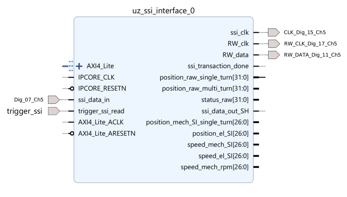
Fig. 418 Example of connecting SSI IP core to channel 1 of digital adapter card slot 5#
First, the IP core has to be added to the block design in Vivado:
In the block design, add an SSI interface IP core
uz_ssi_interfaceinside theuz_userhierarchy.Create pins and connections in the hierarchy according to the figure above.
Additionally provide
100 MHzclock and reset signals for the IP core and the AXI4_Lite interface.Connect the AXI4_Lite interface to the
AXI_SmartConnectblock in the uz_user hierarchy.Outside of the uz_user hierarchy create the respective digital I/O ports and connect them to the digital I/Os of the same name at the uz_user hierarchy.
Connect the
trigger_ssi_readpin to thetrigger_conversionspin of theuz_systemhierarchy.It is highly recommended to also place an integrated logic analyzer block
ILAand connect at least:trigger_ssi_read,ssi_clk,ssi_data_in, andssi_data_out_SH, in order to debug the timing in case of high encoder clock frequencies or long encoder cables. See also Delay Compensation of ssi_data_in.Assign an AXI address, validate the design, save it and generate the bitstream. Perform export of the xsa file after successful generation of the bitstream.
If more than one SSI interface is required, the table below shows the pin assignment for all three channels of the uz_d_absolute_encoder adapter board.
SSI IP core signal |
Channel 1 |
Channel 2 |
Channel 3 |
|---|---|---|---|
ssi_clk |
Dig_15_Chx |
Dig_14_Chx |
Dig_22_Chx |
RW_clk |
Dig_17_Chx |
Dig_16_Chx |
Dig_23_Chx |
RW_data |
Dig_11_Chx |
Dig_10_Chx |
Dig_20_Chx |
ssi_data_in |
Dig_07_Chx |
Dig_06_Chx |
Dig_18_Chx |
Software driver#
The SSI interface driver configures and accesses the SSI IP core from the processor. It writes the encoder configuration, PLL parameters, machine pole pair count and mechanical offset to the IP core. After enabling the IP core, the driver provides separate getter functions for the raw position values, SI position values and speed values. For interacting with the IP core, the following step-by-step example shows a way of implementing one instance of the software driver.
In Vitis, in the Baremetal project under the folder
hw_initcreate a new fileuz_ssi_interface_init.c.Include necessary files and create a
configstruct as well as an init function for one or more instances as shown below:
#include "../include/uz_ssi_interface_init.h"

struct uz_ssi_interface_config_t ssi_d5_1_config = {
    .base_address = XPAR_UZ_USER_UZ_SSI_INTERFACE_0_BASEADDR,
    .ip_clk_frequency_Hz = 100000000U,
    .machine_polepairs = 2U,
    .ssi_clk_frequency_Hz = 1000000U,
    .position_encoding = uz_ssi_interface_binary,
    .position_mech_offset_si_single_turn = 0.0f,
    .ssi_encoder_bit_width_single_turn = 19U,
    .ssi_encoder_bit_width_multi_turn = 0U,
    .ssi_encoder_number_of_status_bits = 0U,
    .kp_pll = 628.3185f,
    .ki_pll = 98696.0f,
    .sampling_interval_seconds = 0.0001f,
    .sampling_delay_clk_ticks = 0U
};

uz_ssi_interface_t* ssi_encoder_init_d5_1(void) {
    return(uz_ssi_interface_init(ssi_d5_1_config));
}
Important
The value of .sampling_interval_seconds must match the period of the trigger_ssi_read signal that triggers the encoder communication.
In the example above, 0.0001f corresponds to a trigger period of 100 us.
The speed PLL uses this value as its integration step time; wrong values directly lead to wrong speed estimates.
Hint
The values for .kp_pll and .ki_pll can be calculated as described in Position to Speed PLL.
The PLL inside the SSI IP core is based on the same implementation, but uses fixed-point math instead of floating-point math.
This can reduce the PLL performance, especially at low speeds.
If maximum PLL performance is required, use the SI position signals from the SSI IP core and calculate the speed with the software implementation of the Position to Speed PLL instead.
Note
The base address is generated by Vivado when the AXI address is assigned in the block design.
After exporting the XSA and updating the Vitis hardware platform, the address macro is available in xparameters.h.
In the example above this macro is XPAR_UZ_USER_UZ_SSI_INTERFACE_0_BASEADDR.
In the
includefolder, create a header fileuz_ssi_interface_init.h.Include necessary files and add the function prototype of your init routine:
#pragma once
#include "../IP_Cores/uz_ssi_interface/uz_ssi_interface.h"
#include "xparameters.h"

uz_ssi_interface_t* ssi_encoder_init_d5_1(void);
In the header file
globalData.h, include header file and add an object pointer of the respective type in theobject_pointer_tstruct as shown below:
...
#include "IP_Cores/uz_ssi_interface/uz_ssi_interface.h"
...

typedef struct{
    ...
    uz_ssi_interface_t* ssi_encoder_d5_1;
    ...
}object_pointers_t;
In
main.c, initialize an instance of the driver and assign it to the object pointer structure in theGlobal_Datastruct inside theinit_ip_corescase and enable the IP core:
...
case init_ip_cores:
...
Global_Data.objects.ssi_encoder_d5_1 = ssi_encoder_init_d5_1();
uz_ssi_interface_enable_ip(Global_Data.objects.ssi_encoder_d5_1, true);
...
break;
In
main.h, include your init header file#include "include/uz_ssi_interface_init.h".In
isr.c, you can now read the AXI output registers of the IP core and use them e.g. for your control algorithm:
...
YourMechPosST = uz_ssi_interface_get_position_mech_si_single_turn(Global_Data.objects.ssi_encoder_d5_1);
YourMechPosMT = uz_ssi_interface_get_position_multi_turn(Global_Data.objects.ssi_encoder_d5_1);
YourElPosST = uz_ssi_interface_get_position_el_si_single_turn(Global_Data.objects.ssi_encoder_d5_1);
YourMechSpeedRPM = uz_ssi_interface_get_speed_mech_rpm(Global_Data.objects.ssi_encoder_d5_1);
...
Notes#
Some implementation details might be worth knowing in order to use the SSI interface correctly.
Aligned wrapping of single- and multi-turn position#
The SSI IP core provides the input of a mechanical encoder offset in the config struct in order
to align the mechanical zero position of the encoder with the magnetic zero position of the machine (.position_mech_offset_si_single_turn).
When using single-turn encoders, the offset value is added to or subtracted from the single-turn position.
When using multi-turn encoders the offset value is computed in such a way that the multi-turn position value always
wraps aligned to the offset shifted single-turn position. The figure below illustrates the behavior.
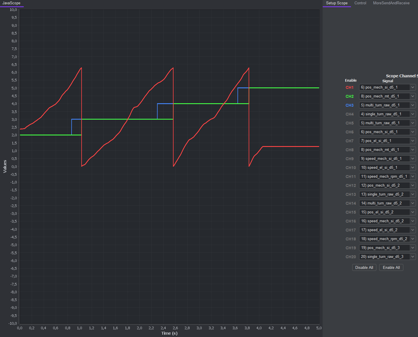
Fig. 419 Illustration of the wrapping behavior of the multi-turn position#
The red signal CH1 is the mechanical single-turn position already accounting for an offset value of -1.0f.
The blue signal CH3 shows the raw multi-turn position, that now would still increment at the \(2\pi\) wrap of the
single-turn position without offset, i.e. at \(2\pi-1.0=5.2831...\). The green signal CH2 is the multi-turn position that accounts for the mechanical
offset value in the config. Its full revolution position counter increments aligned with the red coloured single-turn position.
position_multi_turn is an offset-corrected multi-turn revolution counter which increments aligned with the full revolution wrap of the single-turn position.
It does not contain the single-turn position ticks.
Therefore, when dealing with multi-turn encoders always use the position_multi_turn or position_multi_turn_AXI signal, in order
to have the correct alignment of both single- and multi-turn position. This is exactly the difference between the raw multi-turn value
and the position_multi_turn value.
Validity of position and speed values#
The signal trigger_ssi_read starts one SSI transaction and writes the results of the previous SSI transaction into the output registers.
For example, if trigger_ssi_read is connected to trigger_conversions, the position and speed values are updated once per control cycle.
The software getter functions therefore always read the values of the previous control cycle from the AXI output registers.
This delay has to be accounted for in software if it is critical for control purposes.
ssi_transaction_done only indicates that an SSI transaction is finished and does not indicate validity of the output values.
Delay Compensation of ssi_data_in#
At the clock frequencies of serial encoder interfaces (80 kHz up to 2.5 MHz) the delay of the electrical signals caused by the encoder cables matters. If the time delay is too large, the serial data is no longer sampled correctly by the interface IP core.
Symptom#
The figure below shows an almost edge case, where the sampling will fail when a longer encoder cable is used.
The figure shows the example for an SSI encoder connected with a 1 m encoder cable and a set clock frequency of 2.5 MHz (maximum specified frequency for the respective encoder).
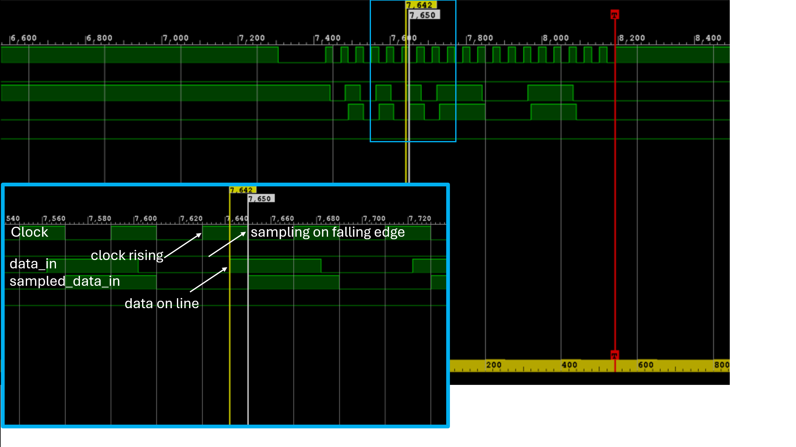
Fig. 420 Sampling mechanism of the serial data from the encoder#
With every rising edge of the clock the next data bit is provided by the encoder clock rising. Due to the internal data transfer logic and the cable delay,
this takes a certain amount of time until the bit is present on the data line in the IP core data_in. In order to give enough time for the bit to show up,
a common practice is to sample the bit at the falling edge of the clock sampling on falling edge. In the figure it can be seen
that only 8 clock ticks before the falling edge the bit is present on the data_in. If we would use a longer
encoder cable, this margin of 8 clock ticks will get smaller until the data bit won’t show up on the data_in line before the falling clock edge occurs.
Debug with ILA#
If you observe invalid behavior of the position values received from the encoder, check the timing of the serial transmission with an ILA in the FPGA block design.
Useful signals are trigger_ssi_read, ssi_clk, ssi_data_in, and ssi_data_out_SH.
Countermeasures#
If possible, reduce the serial clock speed or use a shorter encoder cable.
The IP core driver also provides the config value .sampling_delay_clk_ticks to delay sampling by a certain number of clock ticks after the falling clock edge.
Tune this value while observing the timing with an ILA to compensate for the delay.
Debugging the IP core’s pos_to_speed_pll#
The SSI IP core contains a debug input for the internal pos_to_speed_pll.
This debug path can be used to feed a user-defined mechanical position directly into the speed PLL instead of the mechanical position calculated from the encoder data.
It is useful for checking the PLL parametrization, debugging the speed calculation and separating PLL behavior from encoder communication issues.
The debug path is controlled by the software driver.
Use uz_ssi_interface_set_pll_debug_position to write the mechanical debug position in rad.
Allowed values are between 0 and 2*pi.
Use uz_ssi_interface_enable_pll_debug_mode to switch the PLL input between the encoder-derived position and the debug position.
Warning
If the PLL debug mode is enabled, the speed values no longer correspond to the connected encoder position. Disable the debug mode for normal encoder operation and for closed-loop control with real position feedback. By default, the debug mode is disabled.
Reference#
-
typedef struct uz_ssi_interface_t uz_ssi_interface_t#
Data type for object uz_ssi_interface.
-
enum uz_ssi_interface_position_encoding_t#
Enumeration of the encoding configurations for the SSI position information.
Values:
-
enumerator uz_ssi_interface_binary#
-
enumerator uz_ssi_interface_gray_code#
-
enumerator uz_ssi_interface_binary#
-
struct uz_ssi_interface_config_t#
Configuration struct for uz_ssi_interface.
Public Members
-
uint32_t base_address#
Base address of the IP core
-
uint32_t ip_clk_frequency_Hz#
Clock frequency of the IP core
-
uint32_t ssi_clk_frequency_Hz#
Clock frequency for the serial communication clock, values between 80 kHz and 2.5 MHz are allowed
-
uint32_t ssi_encoder_bit_width_single_turn#
Number of single-turn position bits of the SSI encoder, values from 1 to 31 are allowed. Note that the sum of all bit widths (single-turn, multi-turn, and status) has to be less than or equal to 64
-
uint32_t ssi_encoder_bit_width_multi_turn#
Number of multi-turn position bits of the SSI encoder, values from 0 to 31 are allowed. Note that the sum of all bit widths (single-turn, multi-turn, and status) has to be less than or equal to 64
-
uint32_t ssi_encoder_number_of_status_bits#
Number of status bits of the SSI encoder, values up to 32 are allowed. Note that the sum of all bit widths (single-turn, multi-turn, and status) has to be less than or equal to 64
-
uz_ssi_interface_position_encoding_t position_encoding#
Selects whether the SSI encoder position data is encoded as binary or gray code
-
uint32_t machine_polepairs#
Pole pairs of the machine, only positive values >=1 are allowed
-
uint32_t sampling_delay_clk_ticks#
Delay of the serial data input sampling in IP core clock ticks, values from 0 to 100 are allowed
-
float sampling_interval_seconds#
Sampling interval for the integration employed in the PLL for speed calculation
-
float kp_pll#
Proportional gain for the PI within the PLL
-
float ki_pll#
Integral gain for the PI within the PLL
-
float position_mech_offset_si_single_turn#
Mechanical encoder offset between encoder zero and magnetic zero of the electric machine. Limited to -2*pi … 2*pi and to values that fit into int32_t after conversion to encoder ticks
-
uint32_t base_address#
-
uz_ssi_interface_t *uz_ssi_interface_init(struct uz_ssi_interface_config_t config)#
Initializes an instance of the uz_ssi_interface driver.
- Parameters:
config – Configuration values for the IP core
- Returns:
Pointer to initialized instance
-
uint32_t uz_ssi_interface_get_position_raw_single_turn(uz_ssi_interface_t *self)#
Returns the raw single-turn position read from the SSI encoder.
- Parameters:
self – Pointer to the instance
- Returns:
Raw single-turn position in encoder ticks
-
uint32_t uz_ssi_interface_get_position_raw_multi_turn(uz_ssi_interface_t *self)#
Returns the raw multi-turn position read from the SSI encoder.
- Parameters:
self – Pointer to the instance
- Returns:
Raw multi-turn position in encoder turns
-
uint32_t uz_ssi_interface_get_position_multi_turn(uz_ssi_interface_t *self)#
Returns the offset-corrected multi-turn position from the IP core.
- Parameters:
self – Pointer to the instance
- Returns:
Offset-corrected revolution counter that increments aligned with the full revolution wrap of the single-turn position
-
float uz_ssi_interface_get_position_mech_si_single_turn(uz_ssi_interface_t *self)#
Returns the mechanical single-turn position in SI units.
- Parameters:
self – Pointer to the instance
- Returns:
Mechanical single-turn position in rad
-
float uz_ssi_interface_get_position_el_si_single_turn(uz_ssi_interface_t *self)#
Returns the electrical single-turn position in SI units.
- Parameters:
self – Pointer to the instance
- Returns:
Electrical single-turn position in rad
-
float uz_ssi_interface_get_speed_mech_si(uz_ssi_interface_t *self)#
Returns the mechanical speed in SI units.
- Parameters:
self – Pointer to the instance
- Returns:
Mechanical speed in rad/s
-
float uz_ssi_interface_get_speed_el_si(uz_ssi_interface_t *self)#
Returns the electrical speed in SI units.
- Parameters:
self – Pointer to the instance
- Returns:
Electrical speed in rad/s
-
float uz_ssi_interface_get_speed_mech_rpm(uz_ssi_interface_t *self)#
Returns the mechanical speed in revolutions per minute.
- Parameters:
self – Pointer to the instance
- Returns:
Mechanical speed in rpm
-
uint32_t uz_ssi_interface_get_encoder_status(uz_ssi_interface_t *self)#
Returns the raw status bits read from the SSI encoder.
- Parameters:
self – Pointer to the instance
- Returns:
Raw SSI encoder status bits
-
void uz_ssi_interface_enable_ip(uz_ssi_interface_t *self, bool ip_core_off_on)#
Enables the IP core, i.e., starting the SSI transactions.
The IP core is designed the way that no matter when you turn it on or off,
it will perform enabling or disabling only when there is no SSI transaction happening.
- Parameters:
self – Pointer to the instance
ip_core_off_on – Flag to enable the IP core, false=off, true=enabled
-
void uz_ssi_interface_set_mechanical_offset_ssi_single_turn(uz_ssi_interface_t *self, float position_mech_offset_si_single_turn)#
Sets a new mechanical offset value for the single-turn position.
Values between -2*pi … 2*pi are allowed if the converted encoder tick value fits into int32_t
- Parameters:
self – Pointer to the instance
position_mech_offset_si_single_turn – Mechanical encoder offset between encoder zero and magnetic zero of the electric machine
-
void uz_ssi_interface_set_sampling_delay_clk_ticks(uz_ssi_interface_t *self, uint32_t delay_clk_ticks)#
Sets the sampling delay of the serial data input in IP core clock ticks.
Values between 0 and 100 are allowed.
- Parameters:
self – Pointer to the instance
delay_clk_ticks – Sampling delay in IP core clock ticks
-
void uz_ssi_interface_enable_pll_debug_mode(uz_ssi_interface_t *self, bool debug_on_off)#
Enables or disables the PLL debug mode.
If enabled, the speed PLL uses the debug position instead of the encoder-derived mechanical position.
- Parameters:
self – Pointer to the instance
debug_on_off – Flag to enable the PLL debug mode, false=off, true=enabled
-
void uz_ssi_interface_set_pll_debug_position(uz_ssi_interface_t *self, float position_mech_si)#
Sets the mechanical position used as debug input for the speed PLL.
Values between 0 and 2*pi are allowed.
- Parameters:
self – Pointer to the instance
position_mech_si – Mechanical debug position in rad