Position to Speed PLL#
Tip
Huge thanks to the Department of Power Electronics and Electrical Drives, Paderborn University for providing their implementation as a basis for this software module. The respective literature reference is listed at the bottom of this page.
Description#
The Position to Speed PLL calculates a rotational speed from a rotor position. The calculation is based on a phase-locked loop (PLL). Rotor position sensors often only provide the position signal, but information about the mechanical and electrical rotational speed is also required for control purposes. This software module offers a possible solution for this task. Below, Simulink source of uz_pos_to_speed_pll shows a schematic diagram of the software module with its inputs and outputs.
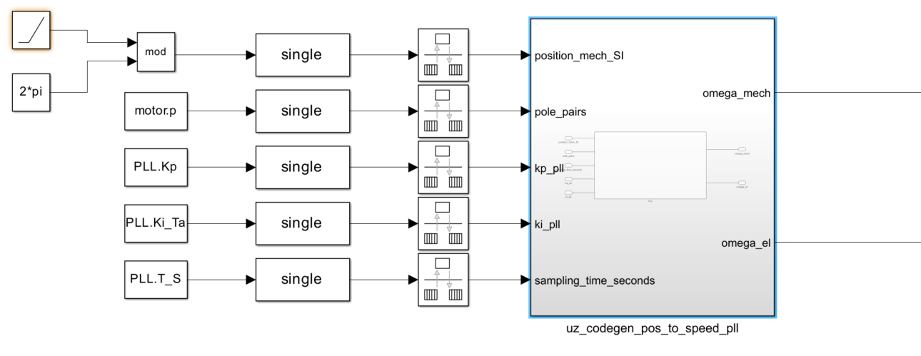
Fig. 399 Simulink source of uz_pos_to_speed_pll#
Interfaces#
Table Interfaces of uz_pos_to_speed_pll module lists all input and output variables.
Variable Name |
Data Type |
Valid Range |
Unit |
Function |
|---|---|---|---|---|
Inputs |
||||
position_mech_SI |
float |
0…2pi |
rad |
Rotational position |
pole_pairs |
float |
>0…floatmax |
1 |
Number of machine pole pairs |
kp_pll |
float |
0…floatmax |
Proportional gain of the PLL |
|
ki_pll |
float |
0…floatmax |
Integrator gain for the PLL |
|
sampling_time_seconds |
float |
>0…floatmax |
seconds |
Sampling time in seconds for the internal integrator |
Ouputs |
||||
omega_mech |
float |
+/- floatmax |
rad/s |
mechanical speed in rad/s |
omega_el |
float |
+/- floatmax |
rad/s |
electrical speed in rad/s |
It is important to note that the input signal for the position, position_mech_SI, must be in rad and must be in the range \(0...2\pi\).
Furthermore, the pole_pairs and sampling_time_seconds must not be \(0\).
Example configuration#
Only a few parameters are necessary to configure the module.
The machine_polepairs parameter must be set according to the electrical machine for which the rotational speed is to be calculated.
The sampling time with which the software module is called must be entered for sampling_time_in_seconds.
For a sampling frequency of 10 kHz, e.g., this is 0.0001 seconds.
The parameters kp_pll and ki_pll have more degrees of freedom and must be adjusted according to the application.
They can be calculated as follows:
where \(d\) is the damping factor and \(f_n\) is the nominal closed-loop frequency in Hz of the PLL.
Useful starting values are \(d=1\) and \(f_n=50\), resulting in \(k_{p,pll}=628.3185\) and \(k_{i,pll}=98696\).
If the stability or dynamics of the PLL are insufficient, the user must adjust the values to the requirements of the application.
The following steps are necessary to use the software module in the ultrazohm_sw framework:
Allow at least one instance of the uz_pos_to_speed_pll software module in
uz_global_configuration.h:
1// Configuration defines for the number of used instance
2..
3#define UZ_POS_TO_SPEED_PLL_MAX_INSTANCES               1U
4..
5#endif
Create a header file
pll_init.hin theincludefolder:
1#pragma once
2#include "../uz/uz_pos_to_speed_pll/uz_pos_to_speed_pll.h"
3
4uz_pos_to_speed_pll_t* pll_0_init(void);
Create a source file
pll_init.cin theswfolder:
 1#include "../include/pll_init.h"
 2
 3struct uz_pos_to_speed_pll_config_t pll_config = {
 4              .machine_polepairs=2.0f,
 5              .kp_pll=628.3185f,
 6              .ki_pll=98696.0f,
 7              .sampling_time_in_seconds=0.0001f
 8};
 9
10uz_pos_to_speed_pll_t* pll_0_init(void) {
11        return(uz_pos_to_speed_pll_init(pll_config));
12}
Add the following code lines to
globalData.h:
1#include "uz/uz_pos_to_speed_pll/uz_pos_to_speed_pll.h"
2
3typedef struct{
4 ..
5 uz_pos_to_speed_pll_t* pll_0;
6 ..
7}object_pointers_t;
Initialize the instance in
main.c:
1case init_software:
2  ..
3  Global_Data.objects.pll_0 = pll_0_init();
4  ..
5  initialization_chain = init_ip_cores;
6 break;
6. Use the instance in isr.c by calling the step-function and assigning an existing mechanical rotor position signal to the module.
Be reminded that the range of the position signal has to be within \(0...2\pi\).
Afterwards read out the electrical and the mechanical speed and assign it to a variable of your choice for further usage:
1  ..
2  uz_pos_to_speed_pll_step(Global_Data.objects.pll_0, encoder_mechanical_rotor_position_signal);
3  Global_Data.av.mechanicalRotorSpeed = uz_pos_to_speed_pll_get_omega_mech_si(Global_Data.objects.pll_0);
4  Global_Data.av.electricalRotorSpeed = uz_pos_to_speed_pll_get_omega_el_si(Global_Data.objects.pll_0);
5  ..
The figure below shows the resulting output mechanical rotational speed in rad/s (green) for an artificial input rotational position signal (blue) at an input step from 1 Hz to 10 Hz:
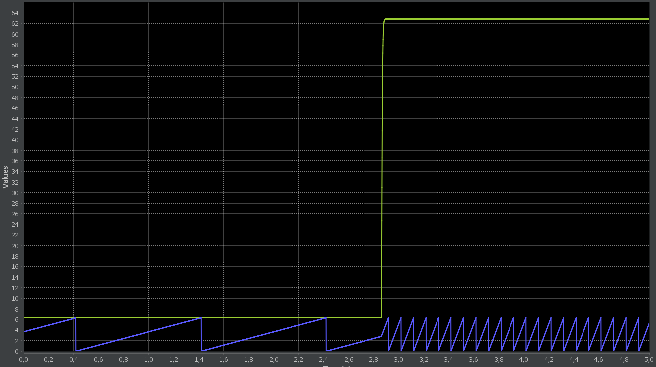
Fig. 400 Result of a test scenario with an artificial input signal to the uz_post_to_speed_pll#
References#
Driver references#
-
struct uz_pos_to_speed_pll_config_t#
Configuration struct for uz_pos_to_speed_pll.
-
typedef struct uz_pos_to_speed_pll_t uz_pos_to_speed_pll_t#
Struct definition for uz_pos_to_speed_pll.
-
uz_pos_to_speed_pll_t *uz_pos_to_speed_pll_init(struct uz_pos_to_speed_pll_config_t config)#
init function for the position to speed PLL
- Parameters:
config – struct uz_pos_to_speed_pll_config
- Returns:
pointer to the instance
-
void uz_pos_to_speed_pll_set_config(uz_pos_to_speed_pll_t *self, struct uz_pos_to_speed_pll_config_t config)#
set function for writing the config parameters to the instance
- Parameters:
pointer – to the instance
config – struct
-
void uz_pos_to_speed_pll_step(uz_pos_to_speed_pll_t *self, float position_mech_si)#
step function. Call periodically in the ISR
- Parameters:
pointer – to the instance
mechanical – position input value in rad, e.g. from a position encoder, Has to be between 0…2*PI
-
float uz_pos_to_speed_pll_get_omega_mech_si(uz_pos_to_speed_pll_t *self)#
get function for the mechanical speed
- Parameters:
pointer – to the instance
- Returns:
mechanical speed in rad per second
-
float uz_pos_to_speed_pll_get_omega_el_si(uz_pos_to_speed_pll_t *self)#
get function for the electrical speed
- Parameters:
pointer – to the instance
- Returns:
electrical speed in rad per second. This value is calculated by multiplying the mechanical speed with the polepairs value from the config struct