How to use FOC for multiple machines#
The following example highlights some key aspects of the UltraZohm, it’s flexibility due to the modular software and hardware as well as the synergy between processors and FPGA. The example is tied to a specific hardware setup but is applicable to any inverter setup. The goal is to control two permanent magnet synchronous machines independent of each other. Each machine is supplied by a two level voltage source inverter and has an incremental encoder.
The following steps are required:
Physical connection of all components
Connect UltraZohm to gate signals of both inverters using Digital Voltage 3U 2v01 on D1
Connect incremental encoders to the Ultrazohm using Digital Incremental Encoder on D5 for first machine and one on D4 for the second machine
Connect phase current measurement of the inverter to the UltraZohm using Analog LTC2311-16 on A1
Connect the input and outputs of the system with the required IP cores using the constraint files
In the setup used for the tutorial, the following mapping of signals applies:
Dig_13_Ch5is the A lane of the incremental encoder of the first machineDig_14_Ch5is the B lane of the incremental encoder of the first machineDig_12_Ch5is the I lane of the incremental encoder of the first machineD4_13(FPGA Pin C12) is the A lane of the incremental encoder of the second machineD4_14(FPGA Pin F11) is the B lane of the incremental encoder of the second machineD4_12(FPGA Pin B11) is the I lane of the incremental encoder of the second machineD1_OUT[5:0] are the gate signals for the first machine
D1_OUT[11:6] are the gate signals for the second machine
Since Digital Incremental Encoder is used on D4 and D5, the CPLD program of D4 and D5 have to be set to
uz_cpld_30rx.jed(see Programming the CPLD)
Vivado#
First, the required IP cores are added that are not present in the Default Vivado project:
Open Vivado
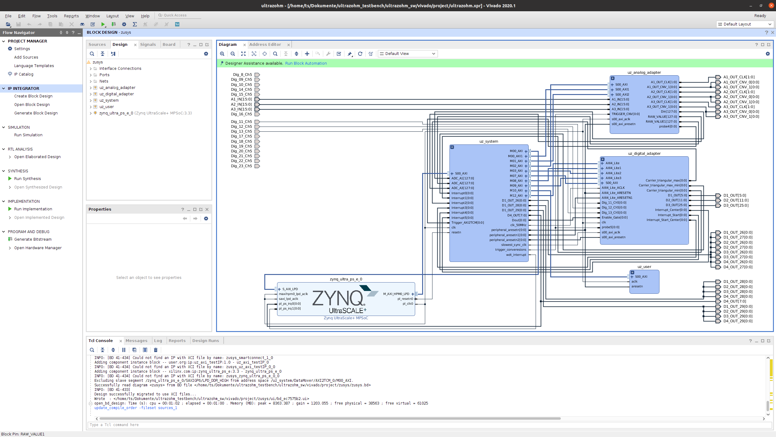
Extend the Vivado subblock uz_user
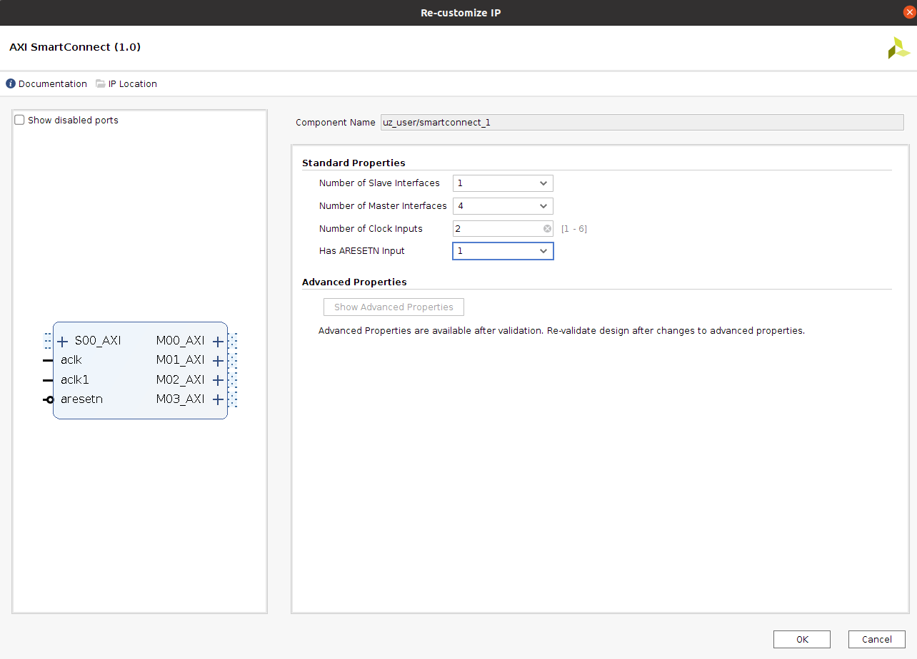
Double click on smartconnect_1, change the number of master ports to 4 and the number of clock inputs to 2
Right click into the uz_user subblock, select Add IP…, and add IncreEncoder_V24 (If a warning regarding duplicate IPs pops up, click Add active ip)
Connect the port aclk1 of smartconnect_1 to the 50 MHz clock of the uz_system subblock
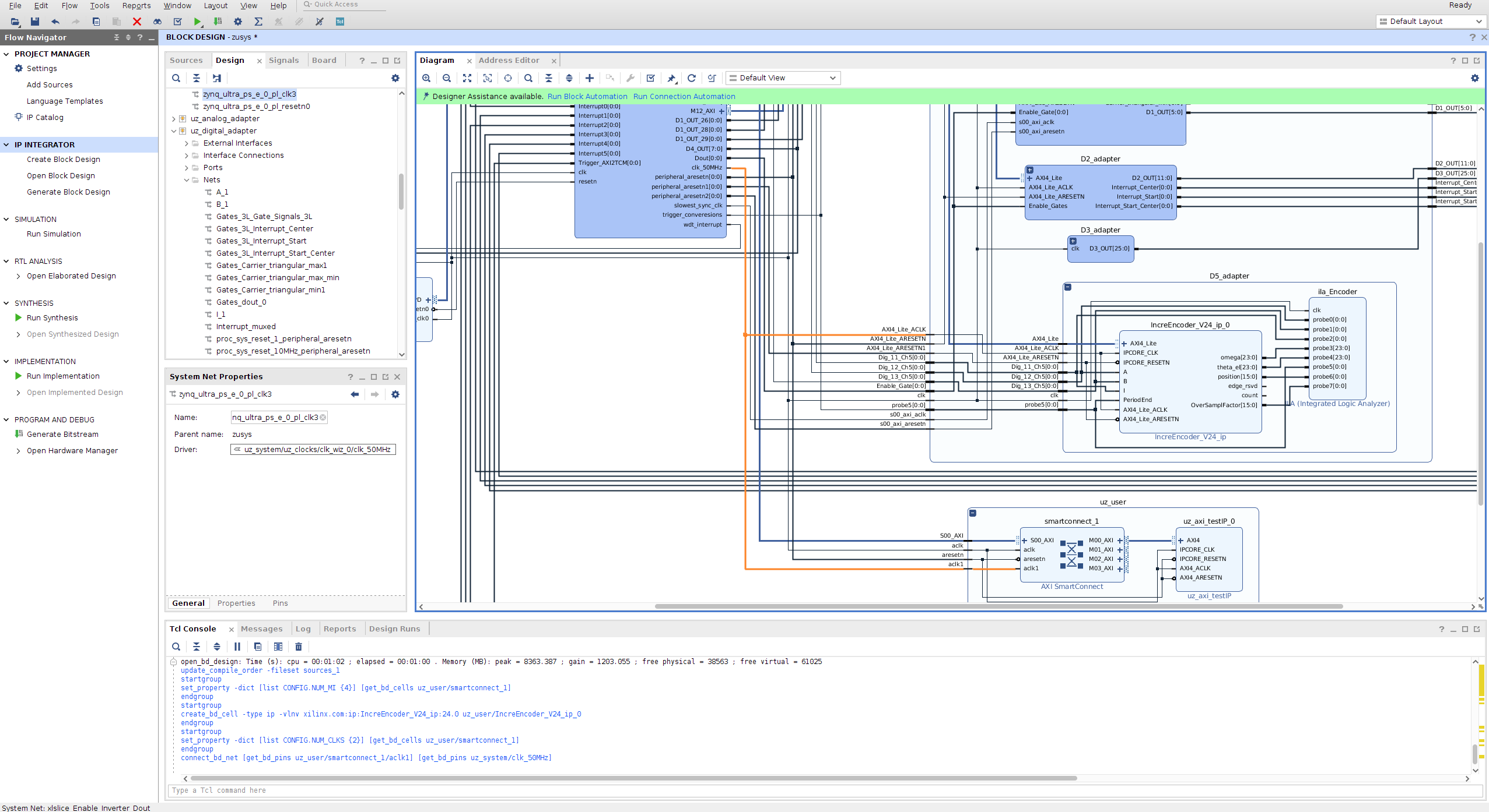
Connect the port aclk1 of smartconnect_1 to the 50 MHz clock of the uz_system subblock

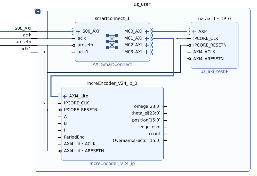
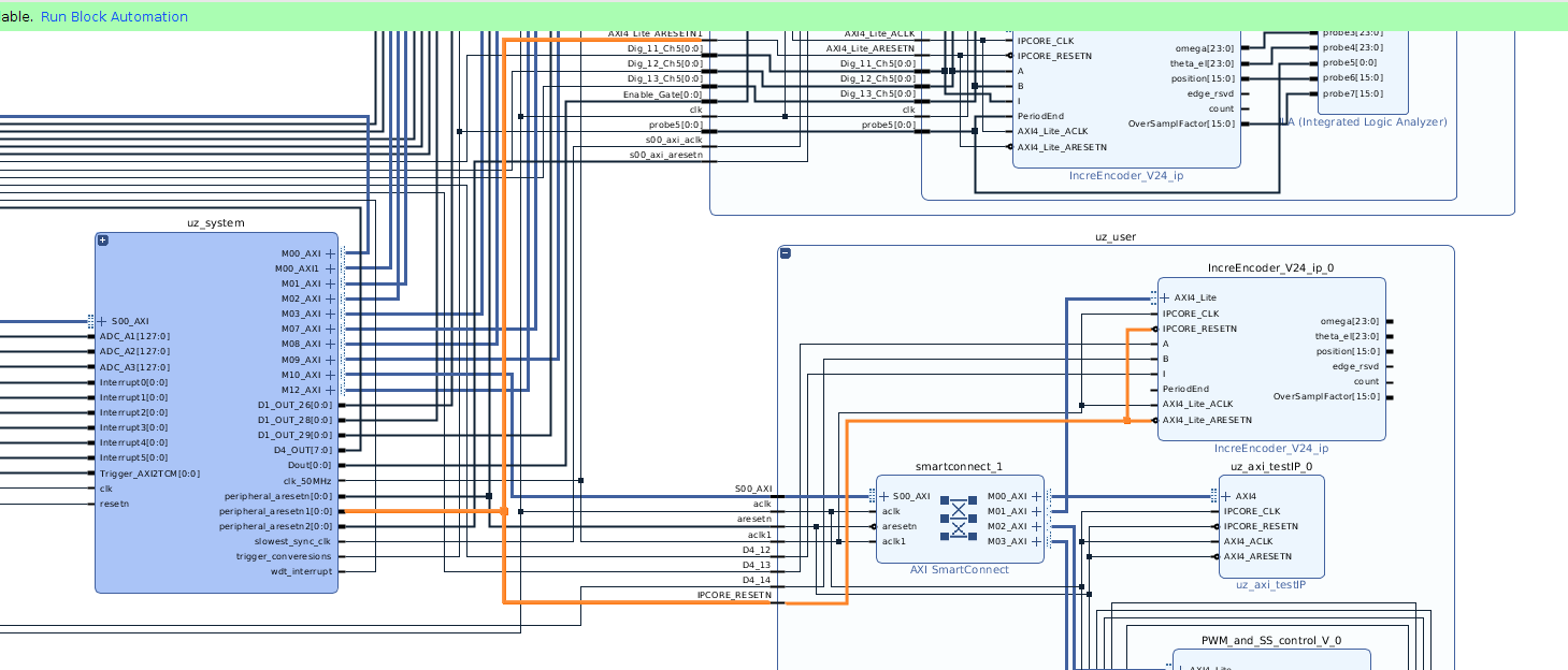
Connect the ports of the incremental encoder as shown in the following picture, i.e., the AXI4-lite port to smartconnect_1, the IPCORE_CLK to the 50 MHz clk and reset to aresetn
Create an input port for D4
Right click, than Create Port, direction is Input, Port name is
D4_13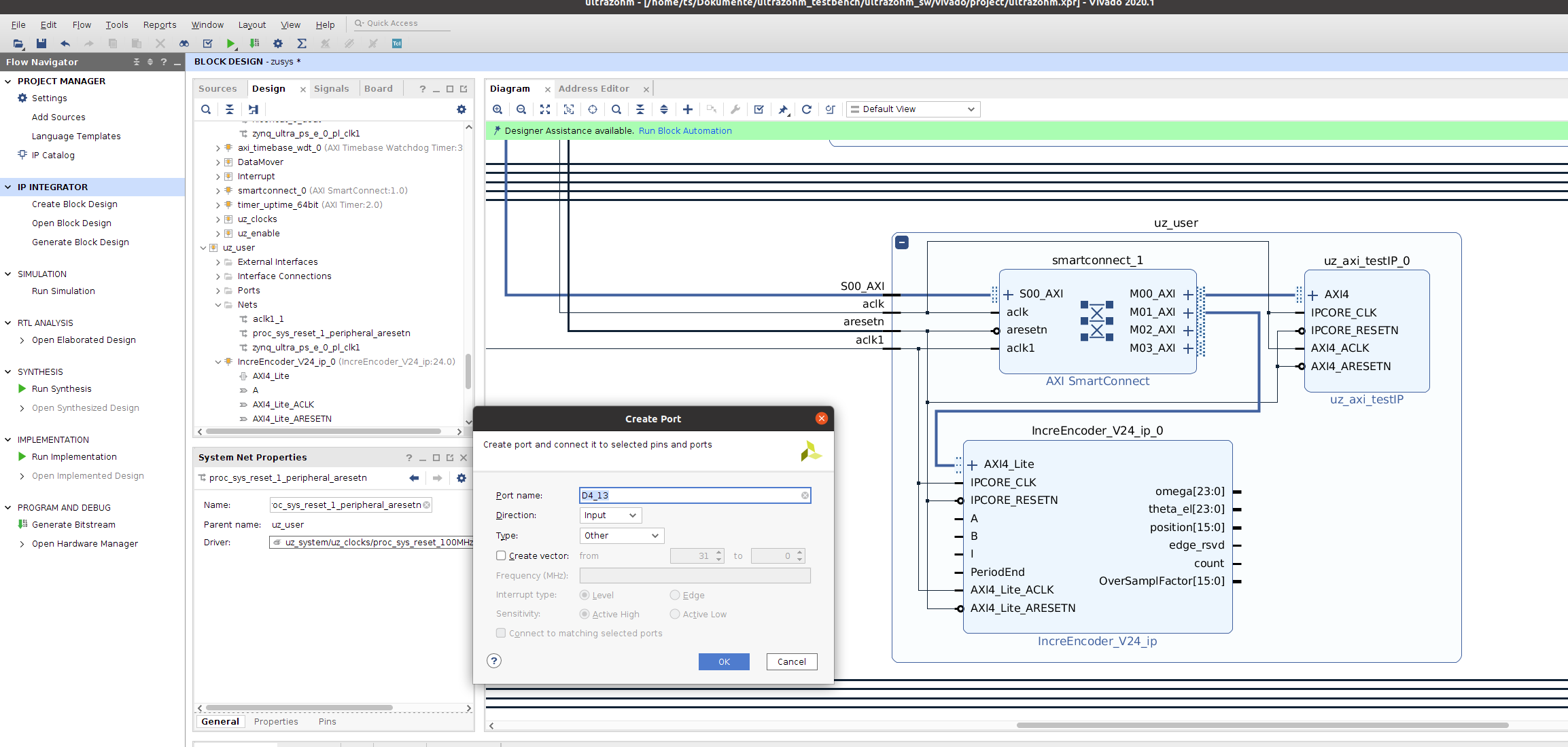
Repeat for
D4_12,D4_14and connect to the IP core according to the pin mapping
Add the IP cores PWM_and_SS_control_V4_ip and uz_interlockDeadtime2L to the uz_user subblock
Connect them to the 100 MHz CLK and AXI ports
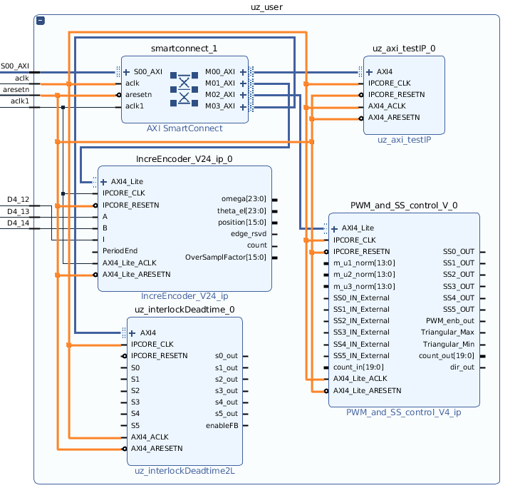
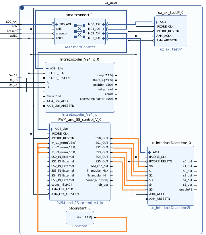
Go to the subblock uz_digital_adapter, D1_adapter, Gates and copy the constant xlconstant_0
Paste the constant into uz_user and connect to m_u1_norm, m_u2_norm, m_u3_norm
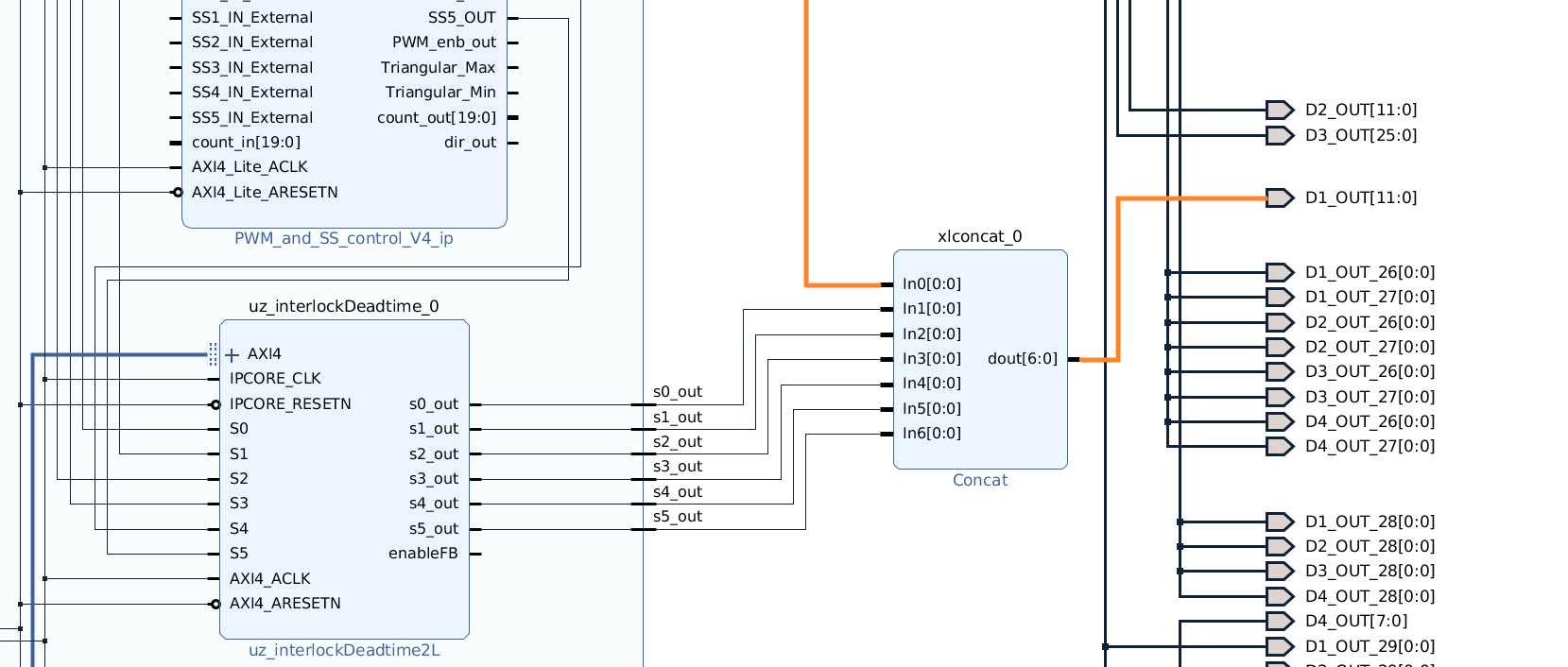
Connect PWM IP core output SS0_OUT to S0 input of interlock IP core, repeat for S0..S5
Go to the connection between uz_digital_adapter and the output port
D1_OUT[5:0]and delete the connectionAdd a new IP core called Concat
Connect in0 of the Concat with D1_out of uz_digital_adapter
Connect dout of the Concat to
D1_OUT[5:0]
Click on
D1_OUT[5:0], go to the External Port Properties and select Properties. Change Left from5to11. This increases the width of the output pins from 6 bit to 12 bit, effectively sending the gate signals of the first inverter to pin 1 to 6 and for the second inverter to pin 7 to 12 on D1.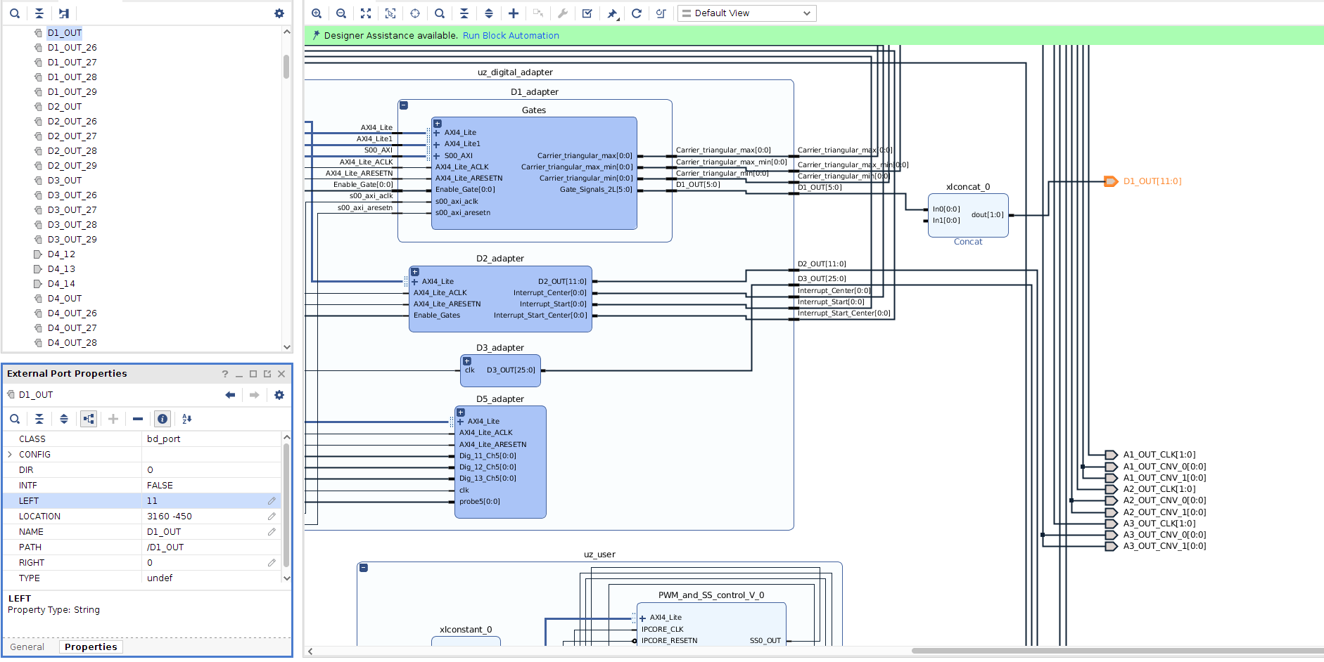
Double click on the Concat and increase the number of ports to 7
Connect In1 to s0_out of uz_interlockDeadtime_0 in uz_user
Connect all other signals, s1_out to s5_out, accordingly to In2…
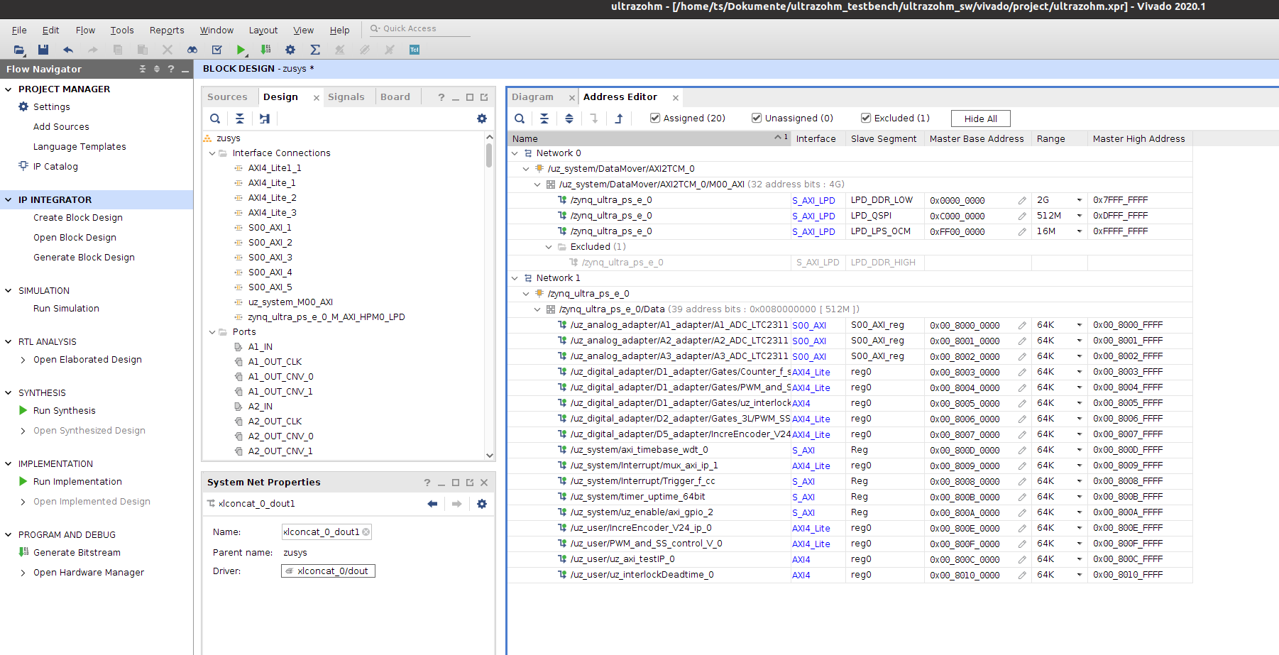
Go the the Address Editor, right click on one of the unassigned signals and click Assign all
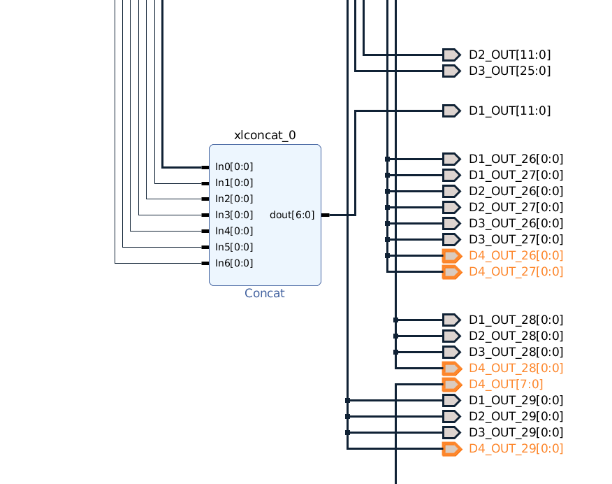
As a last step, the existing output ports for D4 have to be deleted and constraints that match the pin mapping outlined above have to be created. This step is highly specific to the setup that is used and only done in a copy & paste manner
Select all ports that are called
D4_OUTDelete them
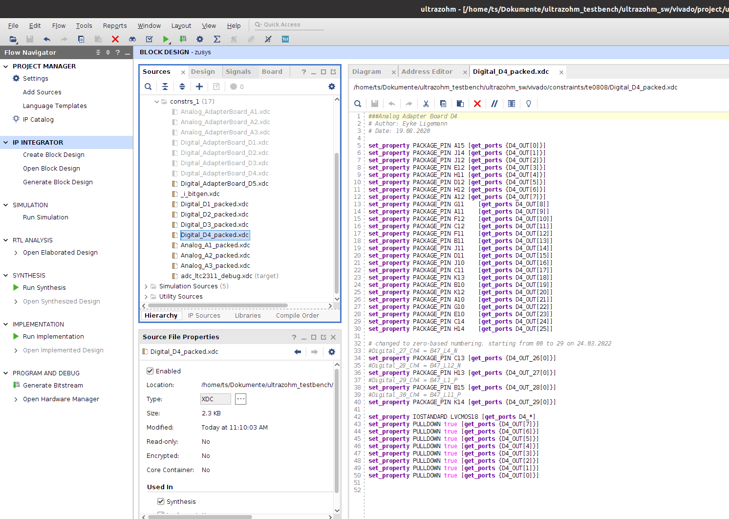
Go to the constraints of D4, delete everything and paste the following code
set_property PACKAGE_PIN C12      [get_ports D4_12]
set_property PACKAGE_PIN F11      [get_ports D4_13]
set_property PACKAGE_PIN B11      [get_ports D4_14]
set_property PACKAGE_PIN J11      [get_ports D4_OUT[14]]

set_property IOSTANDARD LVCMOS18 [get_ports D4_*]
Go to the diagram and press F6 to run the model validation
Notice that there are errors regarding the IPCORE_RESETN pin of IncreEncoder in uz_user
Fix the error by connecting IPCORE_RESETN and AXI4_lite_ARESETN of IncreEncoder to peripheral_areset1 of uz_system
Build the bitstream