Analog LTC2311-16#
Features#
Measurement of 8 differential signals
Sampling rate of up to 5 MSPS
Resolution of 16 bit
Input range is +-5V
ADC LTC2311-16
ADCs are triggered in groups of 4 or 8
Usage of up to three cards possible
Revisions#
The remainder of this page summarizes the analog input connector and measurement modes, which are identical for all revisions of this PCB.
Pinout of Analog Connector#
The pinout of the RJ45 Ethernet plug is NOT intuitive, as shown in Fig. 231.
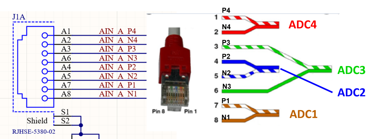
Fig. 231 Pinout of the ADC Ethernet port.#
Note
Note that Fig. 231 shows an Ethernet cable according to T568B!
We provide a breakout board for the RJ45 cable that matches the ADC card. P is the positive analog input, N the negative.
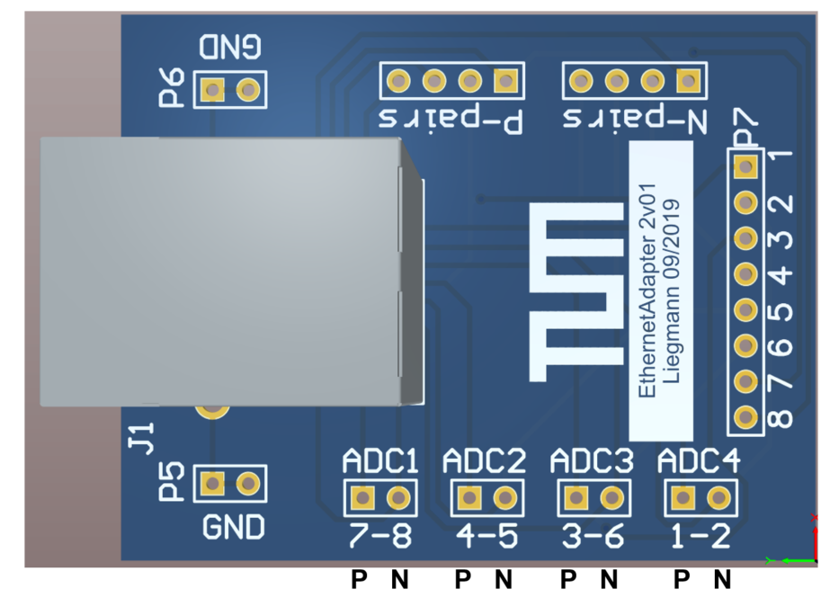
The pairs of the RJ45 Ethernet connector map to the ADCs as follows:
Connected |
Pin on RJ45 |
|
|---|---|---|
ADC |
\(V_\mathrm{in,p}\) |
\(V_\mathrm{in,n}\) |
ADC 1 |
7 |
8 |
ADC 2 |
4 |
5 |
ADC 3 |
3 |
6 |
ADC 4 |
1 |
2 |
Measurement modes#
There are four ways to measure an analog signal with this adapter card
Fully differential
Single-ended with reference to an offset voltage (bipolar)
Single-ended with reference to ground potential (unipolar)
Current signal with a shunt resistor
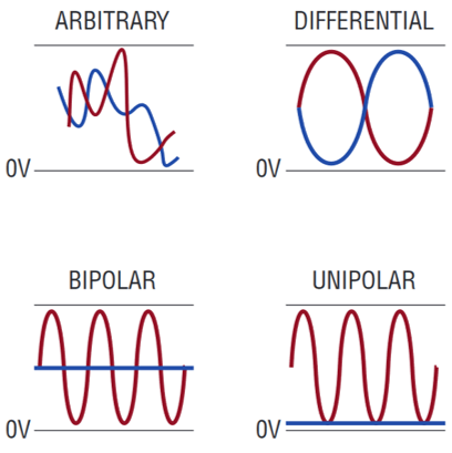
Fig. 232 Different input voltage forms for measurement [LTC2311_datasheet]#
In all cases, the input range is +-5V.
1. Fully differential measurement#
In_P and In_N are fully differential signals, meaning they inverted signals with a common-mode offset of 2.5V, e.g.,
For 0V input voltage, both In_P and In_N are 2.5V
For +1V input voltage, In_P is 3V and In_N is 2V
For -3V input voltage, In_P is 1V and In_N is 4V
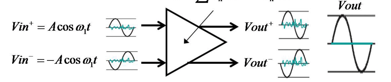
Fig. 233 Fully differential measurement input [LTC2311_datasheet]#
This will yield the highest signal-to-noise ratio (SNR) even when using longer cables. For longer cables, it is recommended to use a differential line driver on the sensing board of this form:
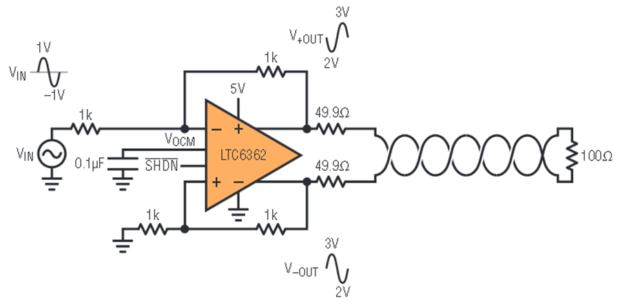
Fig. 234 Signal termination with differential signal over cable [LTC2311_datasheet]#
2. Single-ended measurement with reference to an offset voltage#
The negative input In_N is set to a fixed offset voltage, e.g., 2.5V, which is often provided by the current sensor. The positive input may vary between 0V to 5V. Note that in this case, only 15 bits of the 16-bit ADC are used because the gain of the differential OpAmp is initially set to 1. To overcome this, adjust the gains as described before.
Note
Both voltages should be transferred over the same twisted-pair cable as the positive input In_P, to get the same common-mode noise on both lines, which is then rejected by the differential amplifier.
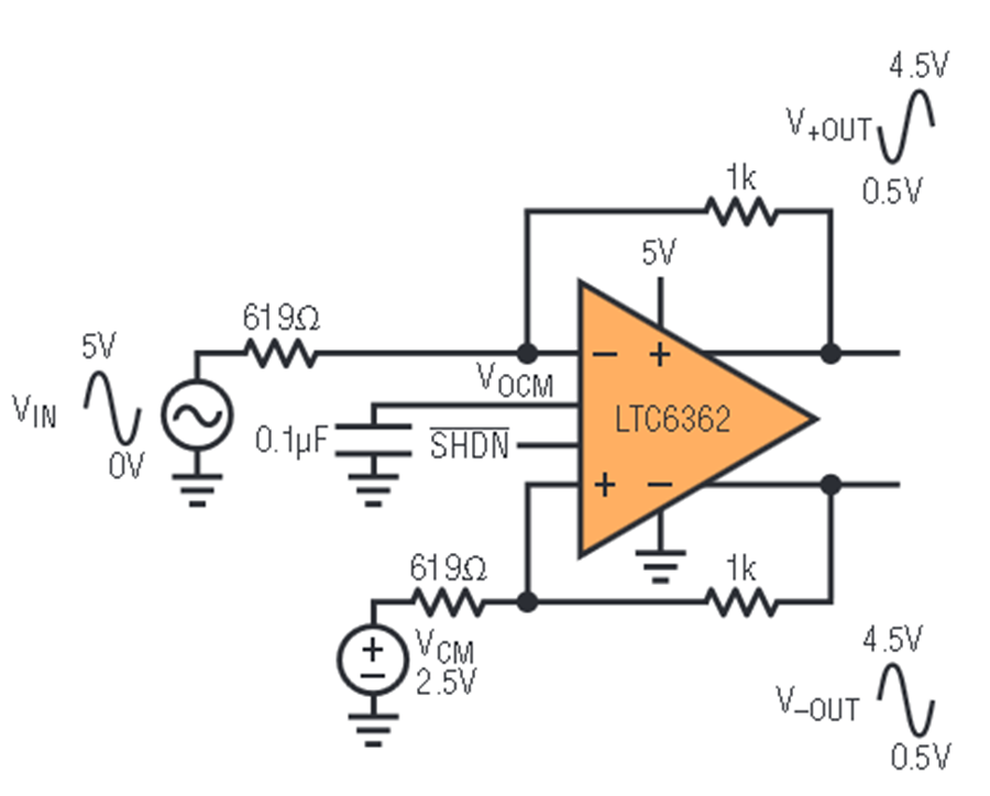
Fig. 235 Single-ended with offset voltage [LTC2311_datasheet]#
3. Single-ended measurement with reference to ground potential#
The negative input In_N is set to ground, which is preferably transferred over the same cable as the measurement signal In_P
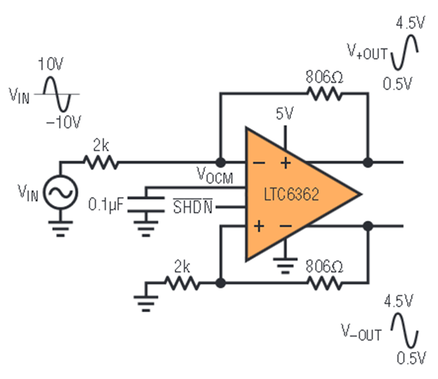
Fig. 236 Usage of the ADC in single-ended mode [LTC2311_datasheet]#
4. Current signal using the shunt resistor R22, R42#
A resistor (package 1206) can be placed between In_P and In_N to terminate a current signal and turn it into a voltage signal that can be measured with this circuit. In this case, the voltage follower is absolutely necessary to avoid an undesired current flow into the differential amplifier. When sizing the resistor, keep in mind that there are two times 100R in series with the input (e.g., R65 and R66). These should be replaced with 0R.
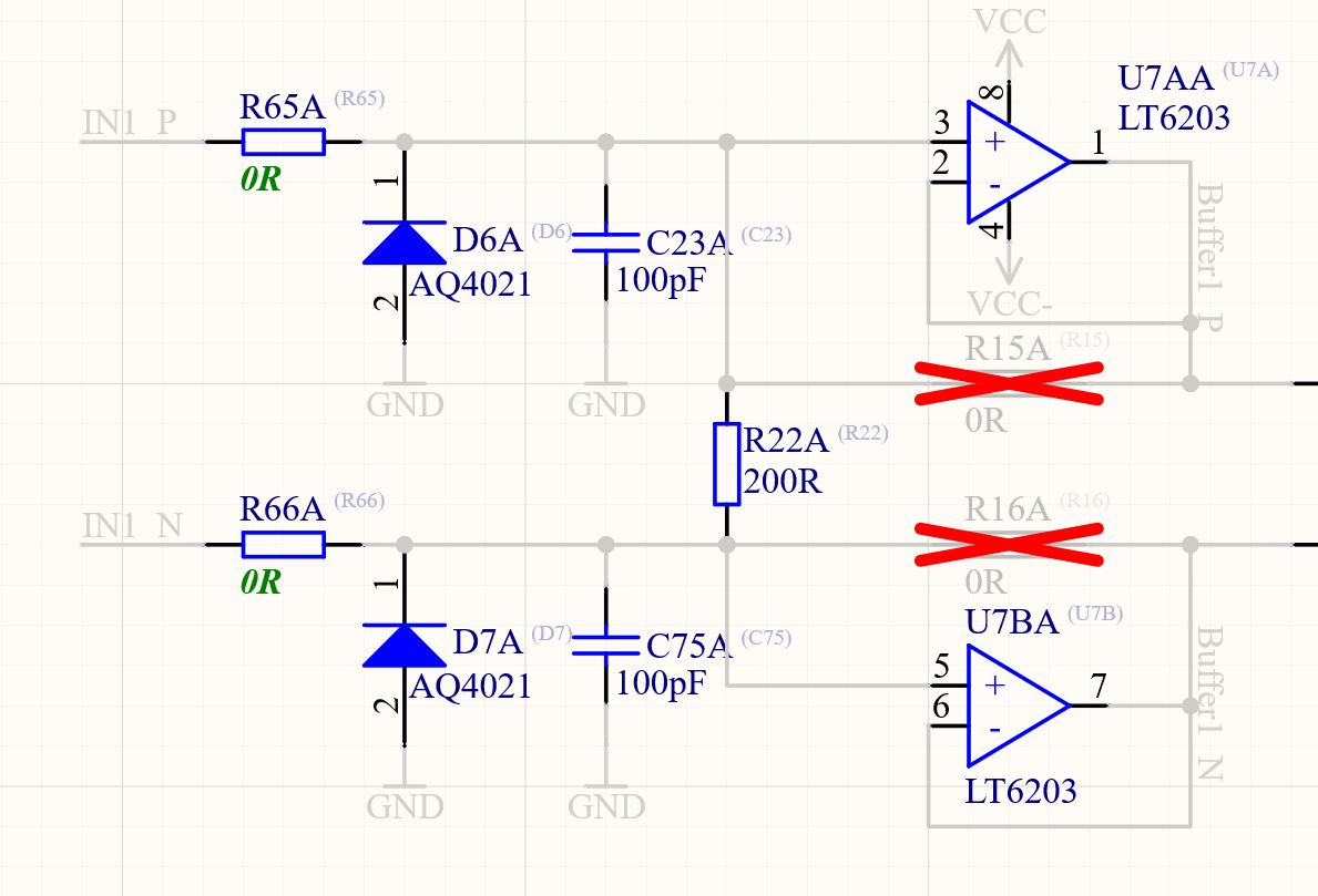
Fig. 237 Assembly of R22 and R42 as shunt resistor for current-based sensors#