Known issues and remedies#
Over-current monitoring vs. unused A slots (Rev05)#
Problem description
The high-side switches used to protect and monitor the VIN rails of the adapter cards also consider “no current” as a fault condition. As all three A slots share a single fault signal (that is connected to the S³C), it is impossible to distinguish an overcurrent condition on (at least) one card from, e.g., only one A slot being used.
The five D slots rely on dedicated signals from switch via slot-local controllers to the S³C, and thus are not affected.
For all slots and the two backpanels, the signal names imply a non-negated signal whilst they – in fact – are negated.
Missing pull-up resistors on spare I²C bus (Rev05)#
Problem description
The I²C bus between the multiplexer on the user bus (I²C0) and the S³C’s secondary controller lacks (dedicated) pull-up resistors (to 1V8). Depending on the chosen bus frequency, this hinders communication between SoM and the – as of mid-2025 unused – secondary I²C of the S³C.
Ethernet PHY Reset pins (≤ Rev04)#
Problem description
The Ethernet PHYs (one or two, dependent on the HW version) own a reset pin RESETn, which should be toggled by a GPIO after power-up. Due to a design mistake, those
RESETn pins were not connected to any GPIO. Therefore, on some UltraZohm systems the PHYs might end up in an undefined state after power-up and not reachable via Ethernet connection.
Remedy
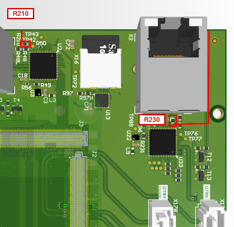
Hardware revision Rev04 (two PHYs):
Replace resistors R210 and R230 with a 10kOhm resistor (package 0603).
Hardware revision < Rev04 (one PHY):
Replace resistor R210 with a 10kOhm resistor (package 0603).
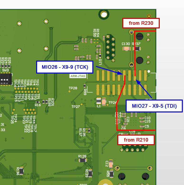
Solder some proper jumper wires to the pads of the resistors as shown below and wrap them around the edge of the carrier board to the bottom side.
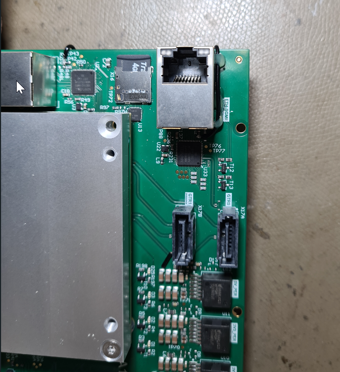
Next, attach them to the respective pads of X9 as shown below.

A proper software driver for toggling the PHY reset pins is shipped by default with ultrazohm_sw v1.0.2 and newer.
This issues is present in version 1v5 to Rev04 and is resolved in revisions newer than that.
For further technical details, see Carrier Board Issue 122
Manual Reset (MR) pin (≤ 3v0)#
Problem description
The MR pin on the JTAG adapter is directly routed to the MR interface on the Trenz SoM. However, there is a mismatch in the voltage level: the JTAG adapter has 1.8V logic level and the MR pin of the SoM is 3.3V logic level.
Warning
This mismatch can lead to unexpected hard resets of the SoM. Clearing the PL and PS configuration (much like turning the entire system off and back on again).
Remedy
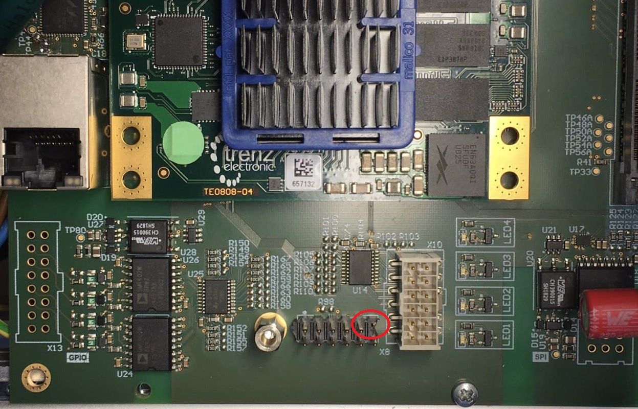
Cut off the MR pin from the JTAG adapter X8-11, as shown below.
This issues is present in version 1v5 to 3v0 and is resolved in 4v0.
For further technical details, see Carrier Board Issue 46
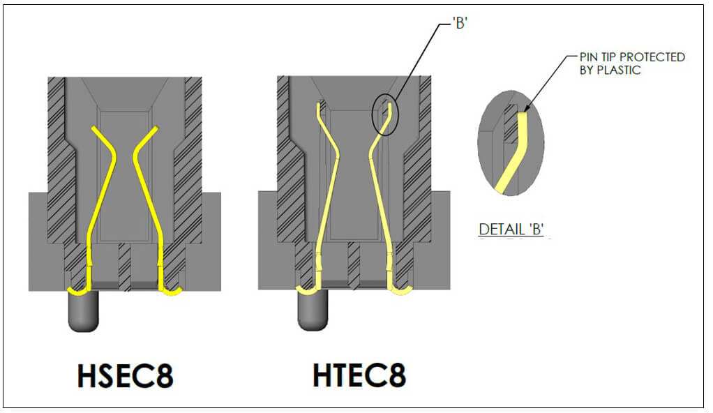
Bent pins in adapter card connectors X5 and X6 (≤ 3v0)#
Problem description
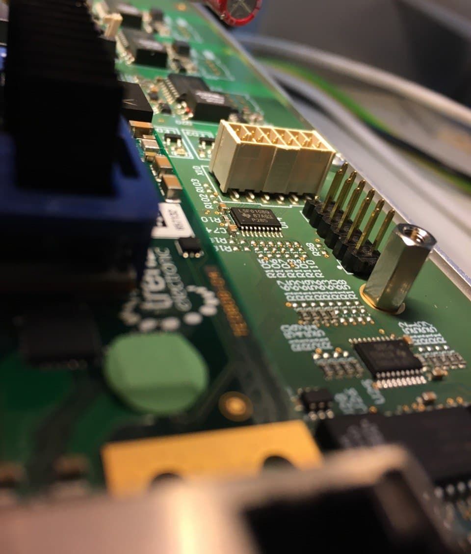
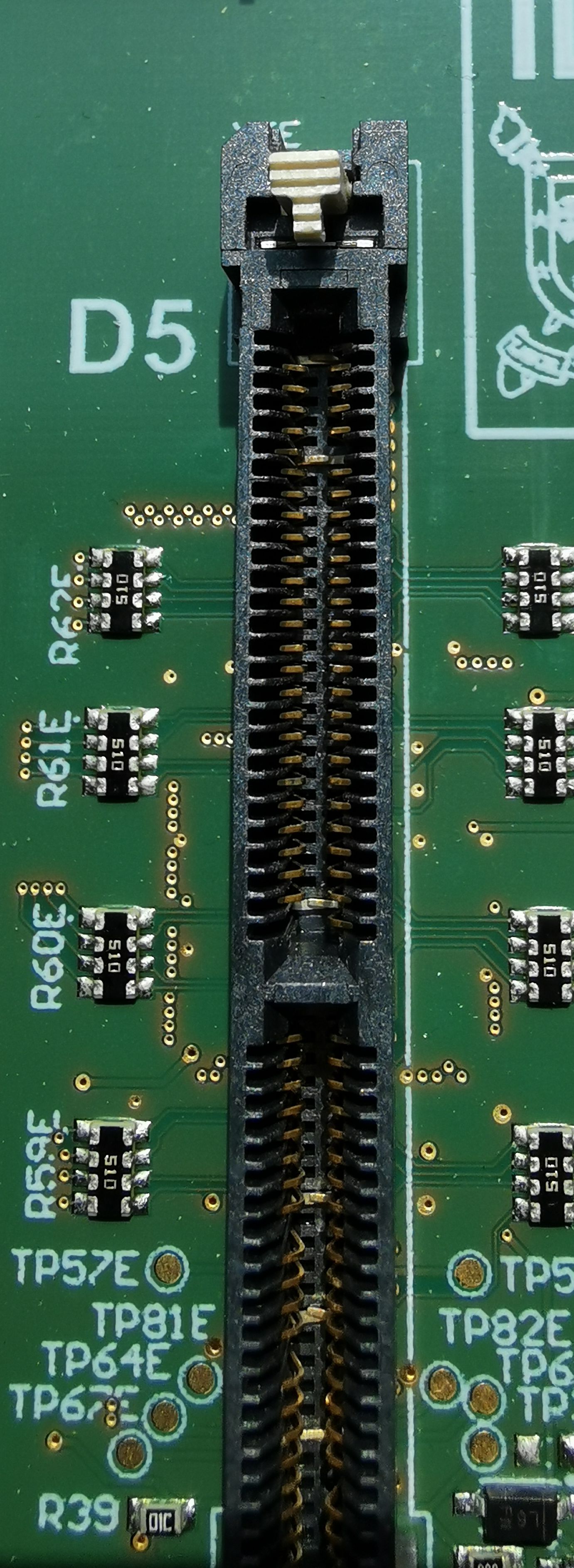
It can happen that the pins on the edge connector sockets X5 and X6 (where the adapter cards are plugged in) are bent downwards, as shown below.
We noticed that this can happen for two reasons:
The mating specified alignment is violated. This can easily happen if the adapter cards are plugged in without using the alignment rails.
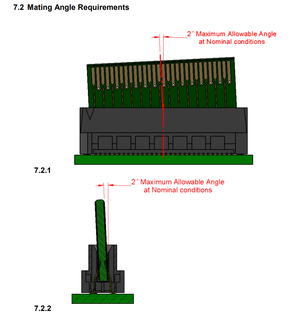
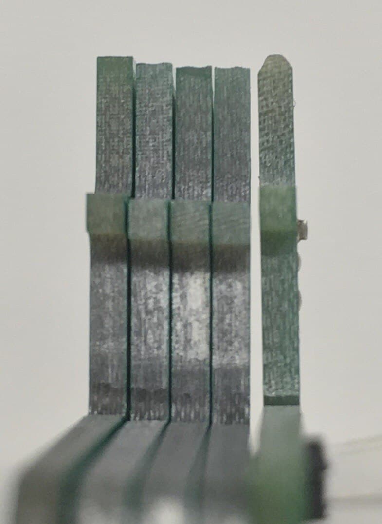
The adapter card does not have a chamfer. The edge connector should have an angled finish. Below shows an example, left without chamfer, right with proper chamfer.
Remedy
Use the alignment rails in the housing when plugging in adapter cards. Do not plug in any cards when the carrier board is not in the housing.
When ordering PCBs for adapter cards, make sure the option “chamfer” is checked, any angle between 30° and 45° works. The PCB thickness should be 1.6mm. With JLCPCB, we had issues that they forgot to add the chamfer even though this was specified in the order. In this case, complain and you will get a replacement or refund.
From carrier board version
4v0and onwards we change to the (pin-compatible) HTEC8 connector. This connector protects the pins from bending and no chamfer is needed. The only drawback is that these connectors do not have the board lock option (yet).
This issues is present in version 1v5 to 3v0 and is resolved in 4v0.
For further technical details, see Carrier Board Issue 17
Level-Shifter not working (≤ 3v0)#
Problem description
Level-Shifters U14, U25, and U30 do not work properly. In the schematic, some resistors are connected at the wrong position.
Remedy
Replace resistors R149, R211, and R225 with 0 Ohm resistor.
This issues is present in version 3v0 and is resolved in 4v0.
For further technical details, see Carrier Board Issue 36
Issues on Carrier Board 1v5#
Warning
Power Mode Dip Switches: EN_GT is disabled, because of a bug in the layout for “EN_GT_L”. Anyway, this is for FireFly and not necessary so far.
Warning
PUDC_B: This issue is only necessary for the carrier board version
1v5!Do not Place R19 at all on the carrier board. Keep the pin open (floating Pin).
The Trenz Module has an internal Pull-Up to 1V8. (Pin J2-127).
Pull-up during configuration (pulled-up to PL_1V8).