Digital IncrEncoder Rev03#
Functionality#
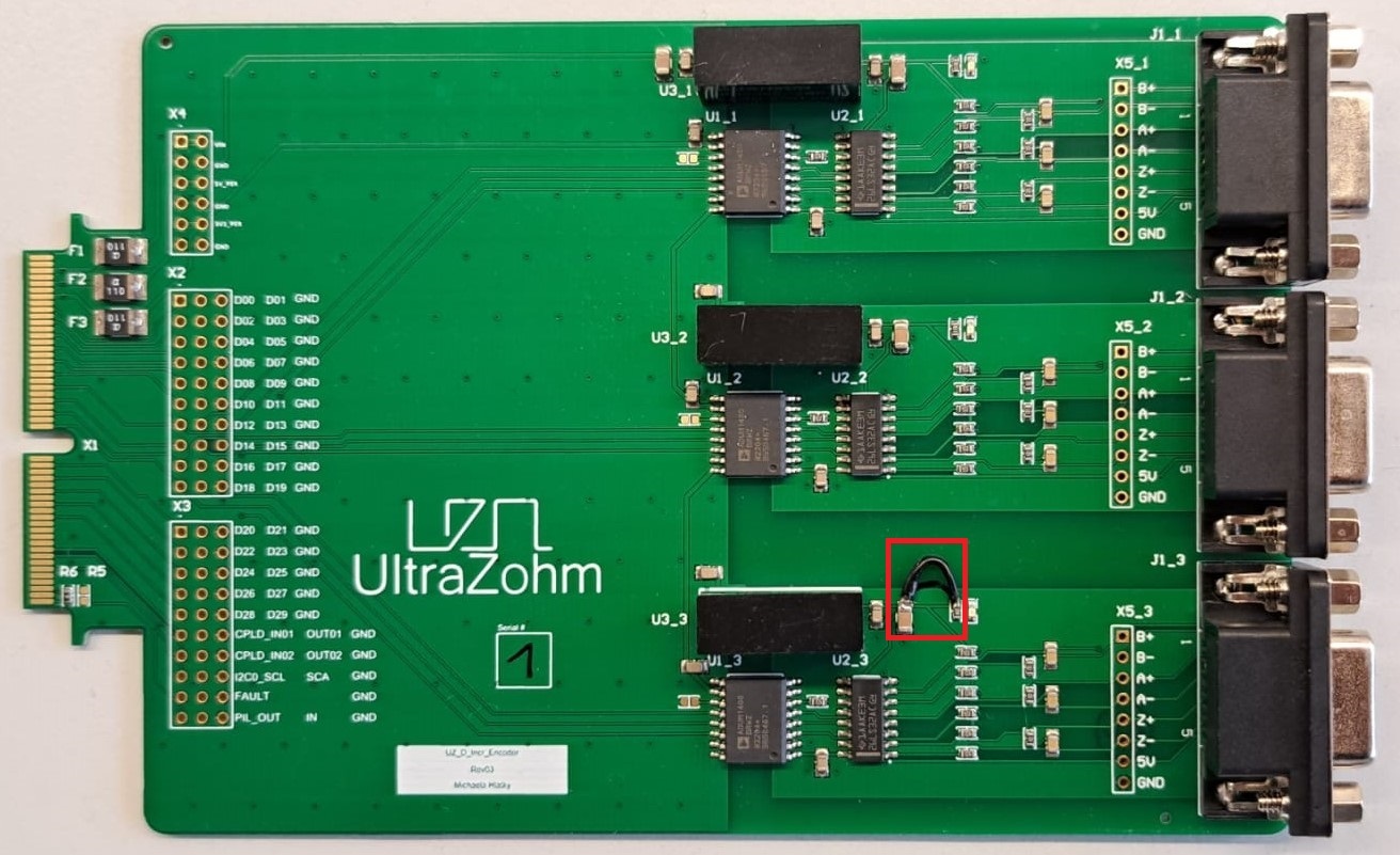
Connects three incremental encoder FPGA
Provides isolated 5V supply to encoder
Reads differential signals from encoder
Pinout (exemplary for Encoder 1)#
Pin |
D-Sub 9 |
FPGA |
Kubrich Encoder |
|---|---|---|---|
0+ |
3 |
Dig_11_Ch5 |
blue |
0- |
4 |
red |
|
A+ |
8 |
Dig_12_Ch5 |
green |
A- |
7 |
yellow |
|
B+ |
5 |
Dig_13_Ch5 |
grey |
B- |
9 |
pink |
|
Vcc |
2 |
brown |
|
GND |
1 |
white |
Pinout (exemplary for Encoder 2)#
Pin |
D-Sub 9 |
FPGA |
Kubrich Encoder |
|---|---|---|---|
0+ |
3 |
Dig_14_Ch5 |
blue |
0- |
4 |
red |
|
A+ |
8 |
Dig_15_Ch5 |
green |
A- |
7 |
yellow |
|
B+ |
5 |
Dig_16_Ch5 |
grey |
B- |
9 |
pink |
|
Vcc |
2 |
brown |
|
GND |
1 |
white |
Pinout (exemplary for Encoder 3)#
Pin |
D-Sub 9 |
FPGA |
Kubrich Encoder |
|---|---|---|---|
0+ |
3 |
Dig_17_Ch5 |
blue |
0- |
4 |
red |
|
A+ |
8 |
Dig_18_Ch5 |
green |
A- |
7 |
yellow |
|
B+ |
5 |
Dig_19_Ch5 |
grey |
B- |
9 |
pink |
|
Vcc |
2 |
brown |
|
GND |
1 |
white |
Program CPLDs with firmware, see Programming the CPLD for details
Known issues#
Rev 03: Not working LED
To get the LED working, an additional connection, marked by the red box in the picture above, has to be soldered to the PCB.
Pin configuration#
Package PIN D5 |
Port |
Signal |
|---|---|---|
J15 |
Dig_19_Ch5 |
Encoder_3_B |
A13 |
Dig_18_Ch5 |
Encoder_3_A |
K15 |
Dig_17_Ch5 |
Encoder_3_I |
B13 |
Dig_16_Ch5 |
Encoder_2_B |
G14 |
Dig_15_Ch5 |
Encoder_2_A |
A14 |
Dig_14_Ch5 |
Encoder_2_I |
G15 |
Dig_13_Ch5 |
Encoder_1_B |
B14 |
Dig_12_Ch5 |
Encoder_1_A |
E15 |
Dig_11_Ch5 |
Encoder_1_I |
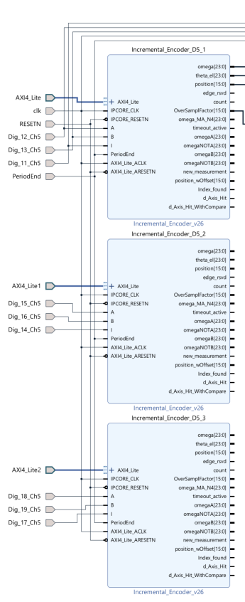
Vivado block design with three IP cores on D5#
For using all channels of the card, the user has to change the block design in vivado (three IP cores on D5 connected).
Compatibility#
Slots D1 to D5 can be used without limitations, D5 is suggested.
Block design in vivado has to be adapted with three IP cores for reading out.
See also#
Designed by#
Michaela Hlatky (THN) in 06/2022