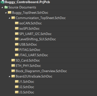
To ensure a better structure and clarity within the individual schematics often a sheet hierarchy is used.
This hierarchy could be designed differently depend on the aim.
One possible structure is shown below:
Top Sheet
Sheet 1.1
Sheet 1.2
Sheet 1.3
Middle Sheet
Sheet 1.4.1
Sheet 1.4.2
Fig. 195 Altium - Hierarchical example of a project structure.#
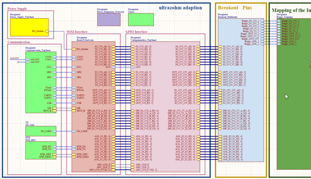
The Top Sheet includes and connects the interfaces of the sheets below and gives a good overview of the general signal flow.
The hierarchy can be designed as deep as the developer it defines, it must not end at the Middle Sheet (shown above).
To define this hierarchy, it is important that you add your necessary schematic sheets one a top sheet.
On the top sheet there is often no information about the different components.
Only information are included about the different schematic sheets, which should be connected.
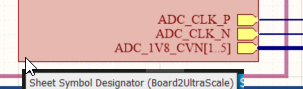
For placing a sheet entry for a schematic sheet, select Place –> Sheetsymbol
Add a designator letter or word (This designator is added behind the main designator, which is annotated in the schematic sheet)
Add the name of the schematic sheet, which should be symbolized.
If you want you can change the color of the boxes, but not necessary.
Place in-/ and output- ports by selecting Place –> Port (for default this port is defined as an I/O Port. If it is only a port in one direction define whether it is an input or an output. This might be helpful by compiling the project.)
In Altium there are different forms of interfaces possible between schematic sheets (individual signals,ports, harness).
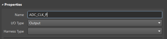
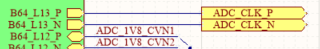
Individual signals can be defined as an input or an output.
To use signals in a top sheet, it is important to define them in the schematic sheet as signals, which are connected to a port.
Output Signal at a schematic sheet. To place a port select Place–> Port.
Bus signals contain many individual signals, which are summarized to one bus system.
With the help of buses the visible clearness is often higher than without.
But handling with bus systems is some times a little bit difficult and depends on the installed version of Altium.
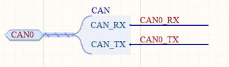
A harness is a container to group different kinds of signals and can summarize signals and bus signals.
A harness is characterized by its defined type.
To create a harness connector select Place –> Harness –> Harnessconnector
If you need more signals in the harness type select Place –> Harness –> Harnessentry
Harness types must also be connect to ports for using them in a global context like Top Sheets etc.
Therefore place common ports. By connecting the common port (often colored in yellow) to a harness, the port will switch the color to blue and the function
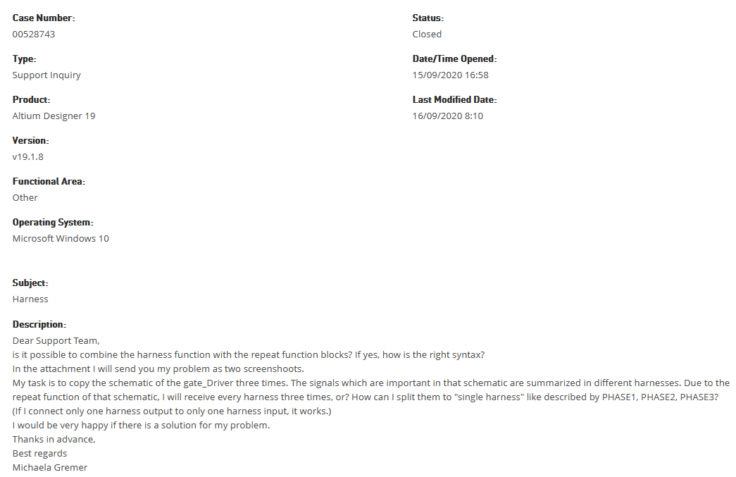
!!!! One important notice: it is not possible with the Altium version 19 to combine harness function with repeat function blocks
Support information from Altium regarding this question:
Fig. 201 Altium - Support information - repeat function and harness.#