System Supply & Safety Component (S3C)#
General#
Device: Lattice Mach XO2
Part: LCMXO2-4000HC-4TG144C
Designator: U19
Supplied by 3V3_S3C, 3V3_PER, 1V8_PER and (if needed) 1V8_S3C
Integrated Flash memory for configuration storage (bitstream)
Programmable via JTAG, SPI (PS-SPI0) and I²C (PS-I2C1)
No external clock source integrated on carrier
Unlike in previous revisions of the UltraZohm,
the frontpanel no longer comes with a red power switch (previously located between the 24V power supply and the carrier), and
the various on-board supplies (derived from the incoming 24V) no longer power up automatically after the 24V are switched on.
Instead, there now are
a “first-level” power switch on the backpanel (as part of the line-supply connector assembly), and
a “second-level” power button on the frontpanel (that replaces the aforementioned red switch).
When the backpanel-side switch is on, the PSU’s 24V only power up a newly-added supply rail dedicated to the S3C (3V3_S3C). All other rails are ramped up as soon as the user presses the frontpanel-side power button, which is monitored by the S3C. Then, the well-known ramp-up sequence of previous carrier boards is started by enabling the now-default-off 3V3_MOD (U10).
Statemachine for S3C#
        stateDiagram-v2

state UZ {
[*] --> Waiting_for_Powerbutton_pressed
Waiting_for_Powerbutton_pressed --> Waiting_for_Powerbutton_released
Waiting_for_Powerbutton_released --> Wait_State
Wait_State --> EthernetPhy_Reset
EthernetPhy_Reset--> Ready_State
Waiting_for_Powerbutton_pressed_2sec --> Ready_State
Waiting_for_Powerbutton_pressed_2sec --> SoftError
Waiting_for_Powerbutton_pressed_2sec --> Warning
Operation --> Waiting_for_Powerbutton_pressed_2sec
        state Operation {
        Ready_State --> Warning
        Ready_State --> SoftError
        Warning --> SoftError
        SoftError --> Warning
        SoftError --> Ready_State
        Warning --> Ready_State
        }
Waiting_for_Powerbutton_pressed_2sec --> Waitingfordslotdown
Waitingfordslotdown --> Waiting_for_Powerbutton_released2
Waiting_for_Powerbutton_released2 --> Waiting_for_Powerbutton_pressed
}
UZ --> HardError
HardError --> Acknowledge_Error
Acknowledge_Error --> Waiting_for_Powerbutton_released2
Powerbutton Functionality#
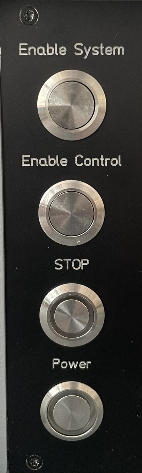
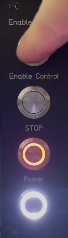
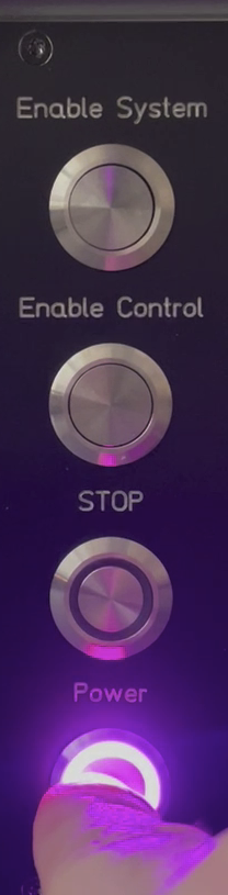
The Power button interacts with the S3C statemachine, and its LED coloring indicates in which state the safety controller currently is.
|
In case the 230V are switched off (via the switch on the backside), the frontpanel will look as shown on the left. |

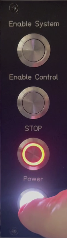
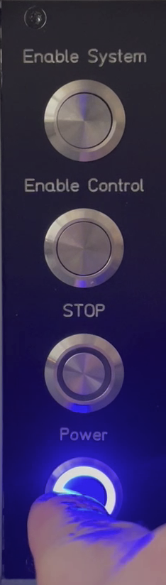
|
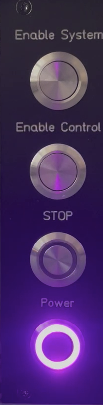
When enabling the 230V on the backside of the UZ with the switch, the S3C is supplied and the Power button indicates this with a blue ring. |
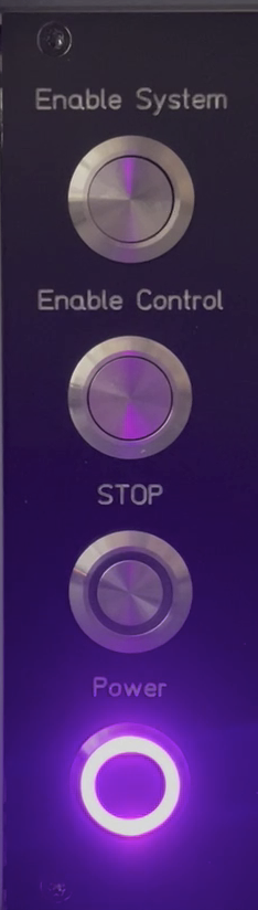
|
The user has to press the button for the system to turn on. This state is indicated by a purple ring. After releasing the button, the system goes into a sequenced power-up procedure. |
|
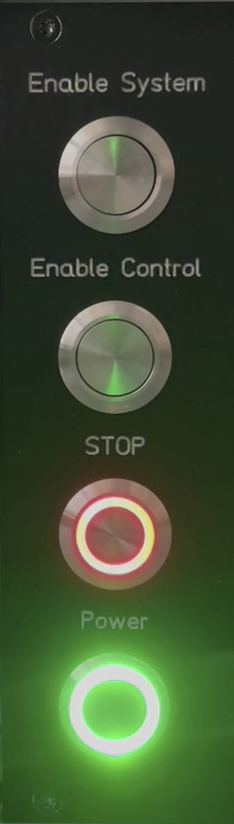
From now on, the system is fully powered on, and the Powerbutton ring is green and the stop button ring is (flashing) red. At this stage, the system can be programmed in Vitis and used in the usual manner. Warning
If the user decides to just use the GUI to enable/control the system and then pushes the stop button there, the behavior will be different to pushing the hardware buttons directly. Only the hardware buttons affect (i.e., set and reset) the hardware release (i.e., are able to return the S3C statemachine from soft errors or warnings back to the ready state), which drives the output enables of the level shifters on new D adapter cards. It thus is not recommended to mix physical control using the buttons on the frontpanel with control via the GUI. E.g., if the control was stopped with the frontpanel’s physical button and the system is then enabled with the GUI, the hardware is not released - Yielding an inoperative state. |
|
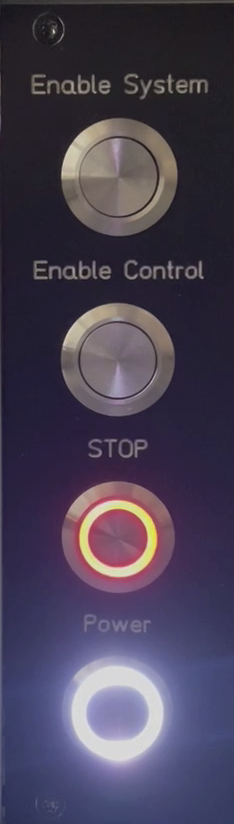
The user can push the stop button and the Power ring will indicate white. |
|
This means that the safety controller commands all five digital slots into their respective safe state. To re-enable the digital slots, there are two possibilities:
|
|
Or:
|
|
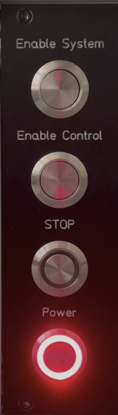
An external emergency can be communicated to the S3C via the external stop connector. The Power button indicates a red light and the S3C brings the system in a safe state. |
|
Once the system is in this state, the user has to acknowledge this error with the Power button. |
|
The S3C gets back into the initial state and the user can power it on as described above. |
|
Regular power off is realized with the Power button. It has to be pushed at least 2 seconds to power off. |
Functions#
Default routes of “pass-through signals”
FrontpanelIO.ExternalSTOP-debounce->FlexMIOs.61_ExternalSTOP(add latch functionality? reset by power cycle?)FlexMIOs.52_PCIe-R̅S̅T̅->FrontpanelIO.FlexMIO52_PCIe-R̅S̅T̅(depending on PS configuration, an inversion might be required)[do not implement until supported by the configuration of the PS!]
SD0_CD(and, later,SD1_CD, if implemented) ->FlexMIOs.45_SD-CD(depending on PS configuration, an inversion might be required)[do not implement until supported by the configuration of the PS!]
FrontpanelIO.isoCtrl.I̅N̅T̅->FlexMIOs.54_I2C0-SharedI̅R̅Q̅
Other defaults
SD_SEL: For the time being, this signal shall be driven to'0'FrontpanelIO.isoCtrl.R̅S̅T̅: For the time being, this signal shall be driven to'1'
Power sequencing
On power-on of the S3C, drive
Carrier_PwrOnlow and keep it there, then check whetherSysSW_Pwr_NCis high (delay required, probably)On a (debounced, cf. above) falling edge on
SysSW_Pwr_NC, initiate the power sequencing (hem) sequence byasserting
Carrier_PwrOn,waiting for
PG_Moduleto (de?)assert, and then, after some ms-range delay,switching
Carrier_PG_1V8(cf. below) from'Z'to'0'for some time and releasing it again (to'Z').Of course, various LEDs are available to signal this process to the user ;-)
For the time being, power-off shall be initiated by a second-long low signal level on
SysSW_Pwr_NC, i.e., holding the power button. For any future versions of this bitstream (on the S3C) anduz_sw(on RPU and APU), a notification to software shall be added (in particular when logging to the SSD is used).Current usage of power good (aka not-reset) signals
Carrier_PG_1V8: Connected toRESETnof the two Ethernet PHYs (carrier and frontpanel-main, 10k pullup on carrier)Carrier_PG_3V3: Enables the DC/DC converter of the isoIO island’s 3V3 rail (on frontpanel-main, no pullup/down R)
Default safety interaction between the System Controller (S3C) and the five D-Slot Controllers
The carrier board’s standard safety concept relies on a fixed set of hand-shake lines that flow between the Digital Slots, the System Controller (S3C), and the D-Slot CPLDs.
The schematic of this interface can be found in the carrier-board design documentation (see page 60 of the PDF)
See Overview of the signal groups between S3C and D-CPLDs below for an extended explanation of the signals
Color |
Conceptual name |
Direction |
Rail |
Explanation |
|---|---|---|---|---|
Black |
5x PILOT_OUT / Output-Enable |
S3C → Slot connector |
3V3 |
Final “enable the card`s outputs” to the slot signal. One line per slot |
Blue |
FLT (Safe-state request) |
S3C → Slot Controller |
1V8 |
Asserted whenever any fault or the external stop asks the whole system to go safe. All slot controllers must react to it |
Purple |
CarrierRdy (x1) |
S3C → Slot Controller |
1V8 |
Tells the slot controller that the main carrier (SoC + power rails etc.) is up and running |
Red |
5x !FLT / per-slot fault |
Slot Controller → S3C |
1V8 |
Each slot pulls its own line low to request a safe state (over-current/temperature/firmware error …) |
Green |
5x OE |
Slot Controller → S3C |
1V8 |
The slot’s internal AND of PILOT_IN (card`s “I’m ready” signal) and its own health. High = “it is safe to enable my outputs” |
Grey |
PILOT_IN (becomes FLT after fusion in slot c.) |
Slot connector → Slot Controller |
3V3 |
just reminds you that the raw card contact is OK; used locally inside each slot controller when it builds its OE and fault logic |
The table above lists every signal, its direction, and its purpose.
These links form the default interaction path implemented in both the S3C bitstream and the D-Slot Controller.
The Request-OE signals (green) – which themselves might depend on the card-local PILOT_IN – effectively are “looped through” the S3C and reach the actual D-Slot slots/cards as Output-Enable (black).
Default logic in the S3C bitstream
The S3C side contains a conditional pass-through that propagates the SlotOE request only when no system-wide force-disable is active:
-- Conditional passthrough for OE
DIGS3C_SlotD_SlotOE <= DIGS3C_SlotD_ReqOE and (DIGS3C_SlotD_SlotOE'Range => NOT forceoutputdisable);
At present, only SlotOE is actively driven. Other potential outputs – such as the S3C’s CarrierRdy – are left unconnected and therefore idle.
Default logic in the D-Slot bitstream
The D-Slot CPLD feeds two status signals back to the S3C:
ReqOE: mirrors the S3C’s output-enable request so the controller can perform integrity checks.
SlotOK: asserted when the S3C has not requested a safe state; it drops low whenever a fault is forced.
Detailed VHDL assignments for the D-Slot Controller are included in Create a CPLD program using Lattice Diamond.
Extending the default behaviour
The current assignments merely establish the mandatory signal directions and the minimal “safe-default” logic. If your application needs tighter supervision or additional routing, you can:
hook extra internal state machines into these nets
expose further pins on the D-Slot connector, or
redefine the pass-through conditions entirely.
In short, while the template guarantees a fail-safe baseline, it is designed to be adapted to any project-specific safety or forwarding requirement.
I/Os#
Static system-level I/O assignment
Inputs
Power sequencing and monitoring:
PWRMON.PG_VIN,PWRMON.P̅P̅_VIN,THERMAL_DATA.S̅H̅D̅N̅,THERMAL_DATA.F̅F̅/F̅S̅,THERMAL_DATA.A̅L̅E̅R̅T̅,PG_ModuleFrontpanel:
FP_UsrSW[1-3],SysSW_Pwr_NC(power button),FrontpanelIO.ExternalSTOPOther system functions:
SD[01]_CD,FlexMIOs.52_PCIe-R̅S̅T̅isoIOs:
FrontpanelIO.isoCtrl.I̅N̅T̅Slots:
ANL_S3C.SlotOK[1-3],DIG_S3C.SlotD[1-5].ReqOE,DIG_S3C.SlotD[1-5].SlotOK
Outputs
Power sequencing and monitoring:
Carrier_PG_1V8and_3V3,Carrier_PwrOnFrontpanel:
FP_SysLED[rgb](RGB LED of power button),FP_SysLEDs(red LED of stop button),FP_UsrLED[1-4]Other system functions:
SD_SEL,FlexMIOs.45_SD-CD,FrontpanelIO.FlexMIO52_PCIe-R̅S̅T̅,FlexMIOs.54_I2C0-SharedI̅R̅Q̅,FlexMIOs.61_ExternalSTOPisoIOs:
FrontpanelIO.isoCtrl.R̅S̅T̅Slots:
ANL_S3C.CarrierReady,ANL_S3C.P54_Legacy,DIG_S3C.Shared.CarrierReady,DIG_S3C.SlotD[1-5].SlotOE,DIG_S3C.Shared.ReqSafeState
Special functions
JTAGENB(see this post in issue 127 for required config. option)Pins 126/125 (primary I²C)
Pins 105/106 (secondary I²C)
Dynamic application-level I/O assignment
FrontpanelIO.isoSigs.FlexIO0[1-5]can be used to drive the last five isoIOs (i.e., fromIO09onwards) as 2x output, 2x input and 1x output (in that order) – So the signal directions are fixed, but function is freely programmableThe six
FlexLIOs[0-5](flexible logic/PL IOs) are available between the S3C (and thus everything reachable from it) and the Zynq’s PLThe S3C’s twelve
DIG5_S3Csignals (00-05, 24-29) complement the SoM’s 18 signals that interface slot D5
Input-specific processing requirements
Do not rely on unless UZ is switched on (i.e.,
Carrier_PwrOnis asserted) AND fully supplied (i.e., no power alert signals are asserted):FP_UsrSW[1-3],FrontpanelIO.ExternalSTOP,FrontpanelIO.isoSigs.FlexIO0[1-5],FrontpanelIO.isoCtrl.I̅N̅T̅,THERMAL_DATA.S̅H̅D̅N̅,THERMAL_DATA.F̅F̅/F̅S̅,THERMAL_DATA.A̅L̅E̅R̅T̅, and - to a certain extent -PG_MODULEIn transitionary states (e.g., the system is losing its supply), additional care is required for all signals as their respective supply rails might ramp down in an instance-variant manner
Debounce filtering:
SysSW_Pwr_NC,FP_UsrSW[1-3],FrontpanelIO.ExternalSTOP– Note that all the above signals are low-active, i.e., high as long as the corresponding button is not pressed
Output-specific processing requirements
Set to
'Z'unless UZ is switched on (i.e.,Carrier_PwrOnis asserted):FrontpanelIO.isoSigs.FlexIO0[1-5],FrontpanelIO.isoCtrl.R̅S̅T̅,FrontpanelIO.FlexMIO52_PCIe-R̅S̅T̅– Note that the above list will get considerably longer if R44 is populated (instead of R43). In that case, care has to be taken w.r.t. S3C bank 2 (i.e., U19C) driving current into powered-off components!