Digital Optical 18Tx_14Tx4Rx 3v01#
Functionality#
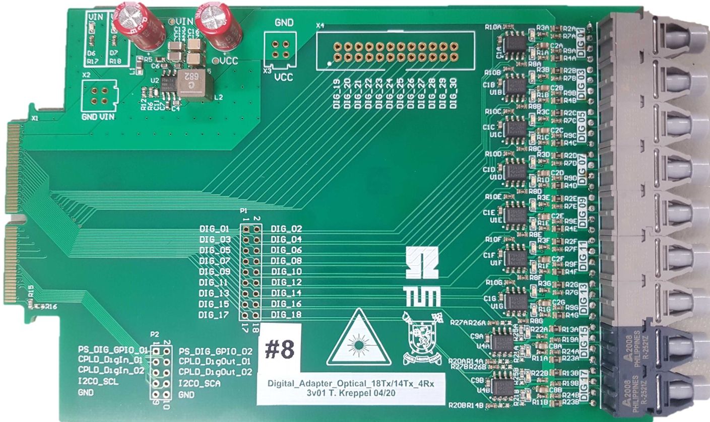
Standard configurations transmits up to 18 optical signals, e.g. gate signals.
Can be modified to receive up to 4 optical signals, e.g. error signals.
LEDs on PCB signaling the state of the transmitter
Logic table#
Transmitter Logic#
GATE Logic HIGH = LED/Transmitter ON
GATE Logic LOW = LED/Transmitter OFF
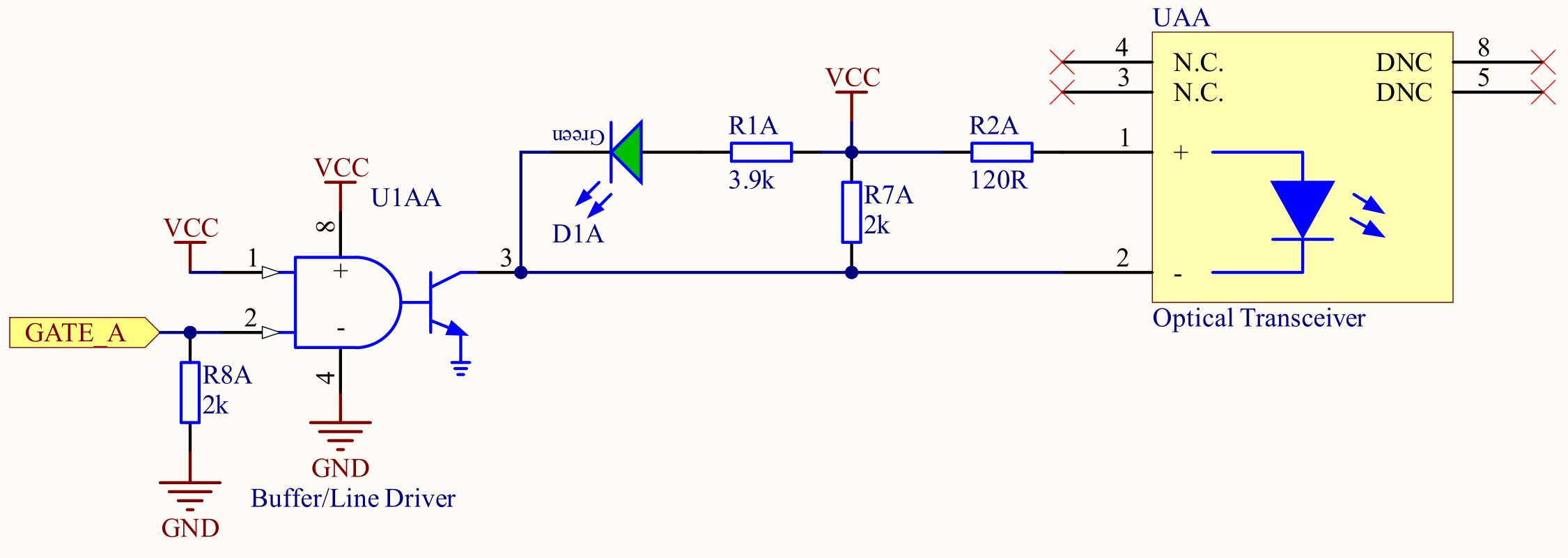
GATE_A |
Output of U1AA (pin3) |
LED D1A |
Transmitter LED UAA |
|---|---|---|---|
LOW |
HIGH |
OFF |
OFF |
HIGH |
LOW |
ON |
ON |
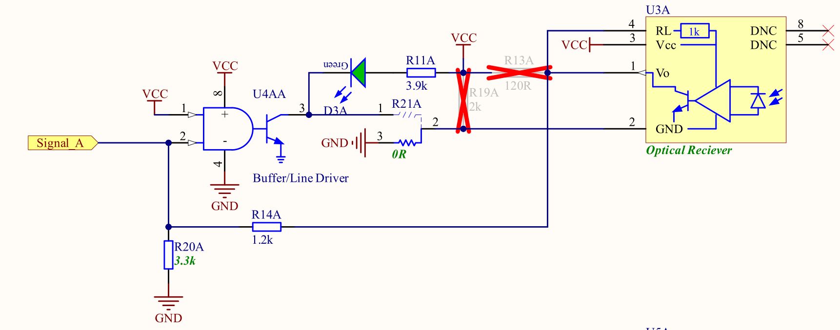
Receiver Logic#
Warning
The receiver logic is inverted!
Receiver Light ON = Signal_A Logic LOW
Receiver Light OFF = Signal_A Logic HIGH
Receiver Diode U3 |
Signal_A |
LED D3 |
|---|---|---|
Light ON |
LOW |
ON |
Light OFF |
HIGH |
OFF |
Before first use#
Soldering#
Solder in up to 18 transmitters Broadcom HFBR-1521Z. Please refer to this page for detailed Soldering instructions.
Program CPLDs#
Program CPLDs with firmware, see Programming the CPLD for details. Note, that the signals are simply passed through the CPLD.
Optionally, additional functionality can be implemented in the CPLD, e.g. checking for invalid switching combinations or introducing a dead time.
(optional) Manual rework allows to exchange the 4 receiver channels to 4 transmitter channels, resulting in up to 18 transmitter channels, check Schematic and Assembly Drawing at the end of this page for the necessary changes.
Additional features#
Manual rework allows to exchange the 4 transmitter channels to 4 receiver channels, resulting in 14 transmitter and 4 receiver channels. To change from transmitter to receiver, you need to change the following components:
Unsolder R13, R19, R23, R24
Change solder position of R21 and R25 to the lower pads
Solder in 1 kilo Ohm for R14 and R26
R20 and R27 may remain as is, 2kOhm.
Solder in optical receivers Broadcom HFBR-2521Z instead of the transmitters.
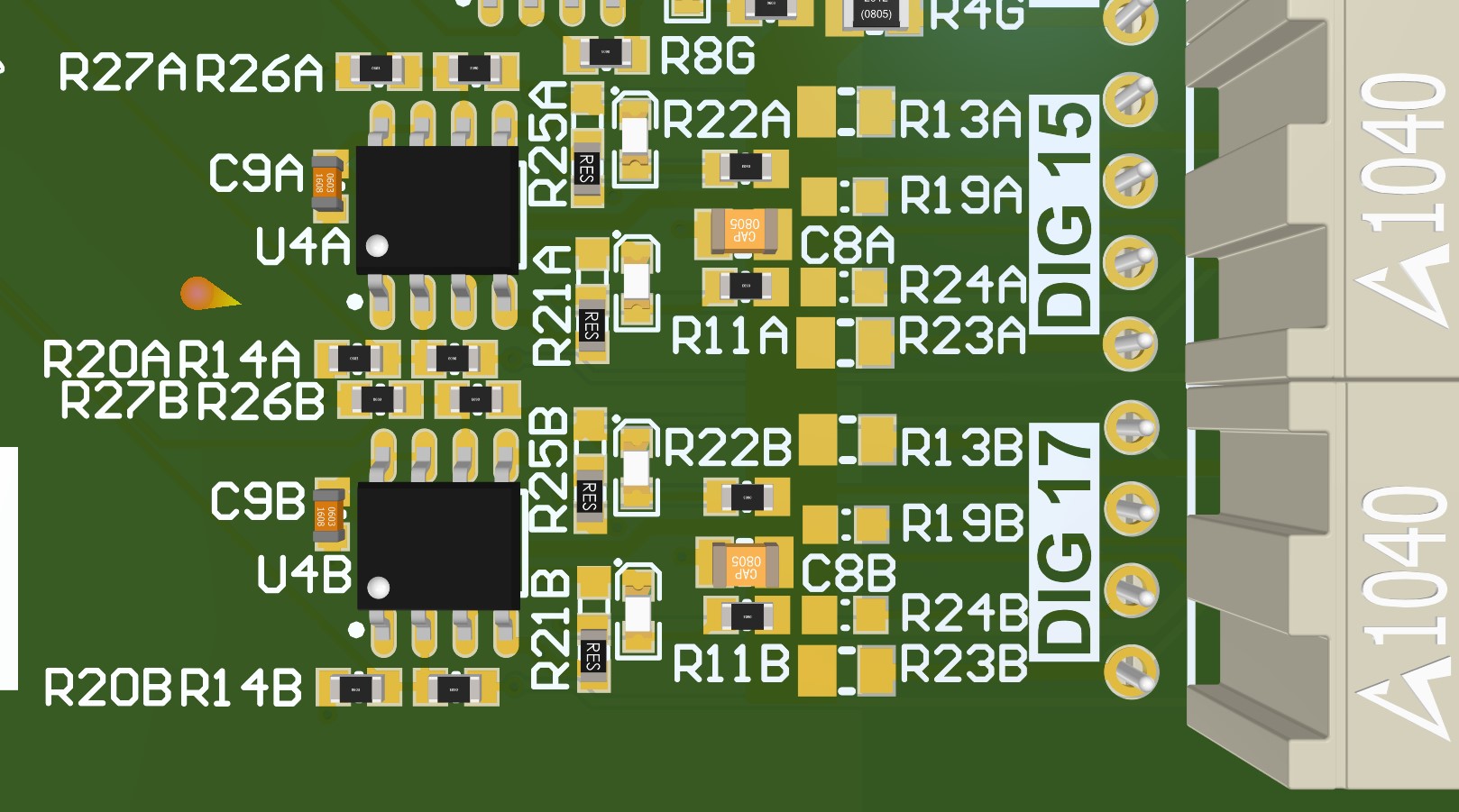
Also check Schematic and Assembly Drawing at the end of this page for the necessary changes.
Known issues#
No known issues
Compatibility#
Slots D1 to D4 can be used without limitations, if CPLD is programmed correctly
Optical Cables#
Optical Cables of type HFBR-RNSxxxZ are tested and recommended for transmitting the optical signals. The xxx determines the length of the cable in meters.
References#
Designed by#
Eugen Romanschenko (TUM), Eyke Liegmann (TUM) in 04/2021