Torque Box PCB#
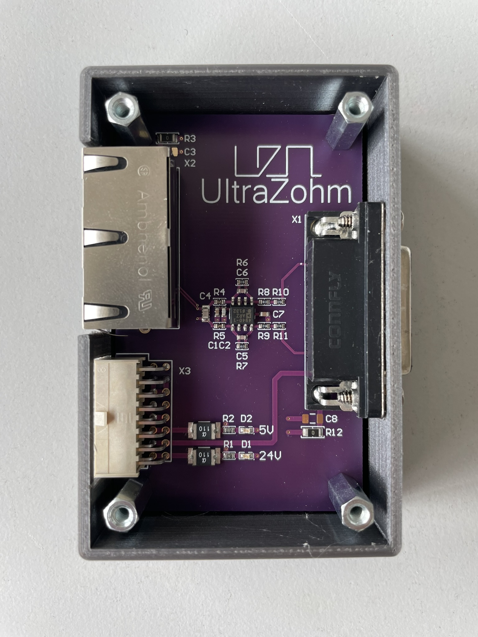
Fig. 292 Torque Box PCB#
Source#
General description#
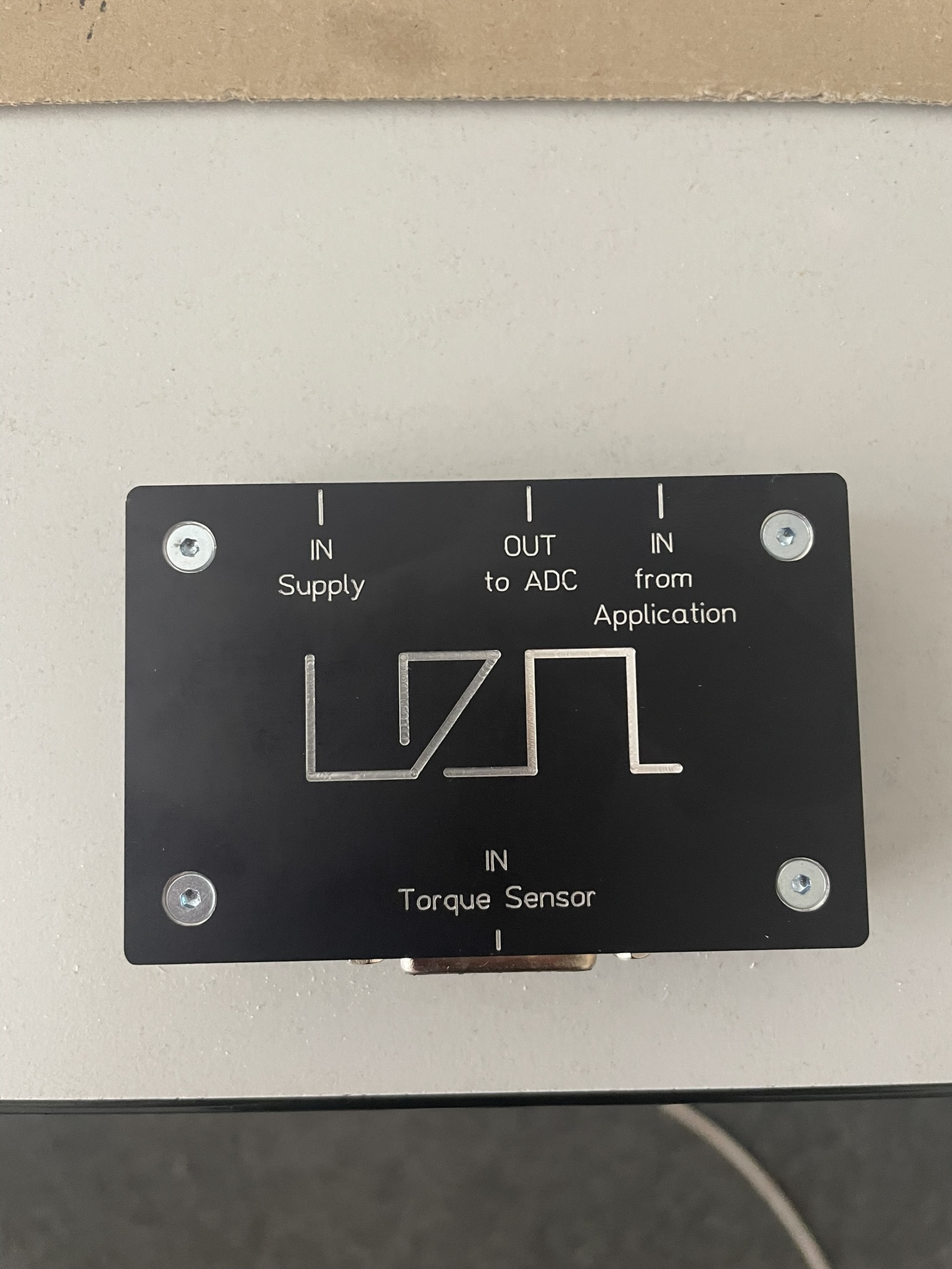
This PCB is designed to supply external torque sensor Burster 8656 Torque Sensor and send the signals to the Analog LTC2311-16 card. The supply is taken from the voltage interface connector of an Analog LTC2311-16 board. The torque signal (+-10V) is reduced to a level of +-5V and low-pass filtered. The torque signal is connected to ADC1 channel of Analog LTC2311-16 and the remaining 3 Channels ADC2-ADC4 can still be used without limitations.

Fig. 293 Functional areas of the uz per torque pcb#
Layout#
The PCB is structured by functional areas as shown in Fig. 293 on the right.
Double Ethernet connector to the ADC adapter board
Measurement signal adaption to +-5V and low-pass filtering (708 Hz).
Supply voltage 24V and 5V from ADC Card with Samtec cable
MMSD-08-28-F-xx.xx-D-K-LDXConnector to the Torque Sensor D-Sub 15
Assembly and Connection#
A 3D-printable housing and an engraved aluminum cover designed for the uz_per_torque_box PCB. The assembly with all necessary parts, including a bill of materials (BOM), is shown below. The PCB can be used without the housing, but it is more rugged and much more beautiful with the housing.
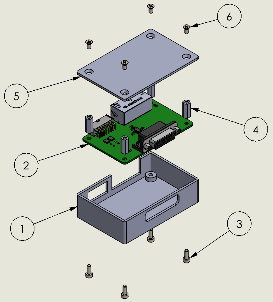
Fig. 294 Assembly drawing of the torque_box#
No |
Description |
Manufacturer Part Number |
Amount |
Hint |
|---|---|---|---|---|
1 |
Housing body |
housing_body.STL |
1 |
Print on any FDM printer with PLA material |
2 |
PCB |
uz_per_torque_box |
1 |
|
3 |
Socket head cap screw |
EN ISO 4762 M3x8 |
4 |
|
4 |
Würth Steel spacer stud M3x14 |
970140321 |
4 |
|
5 |
Housing cover |
uz_per_torque_box.fpd |
1 |
Order at Schaeffer AG |
6 |
Countersunk flat head cross recess screw |
DIN EN ISO 7046-1 M3x6 |
4 |
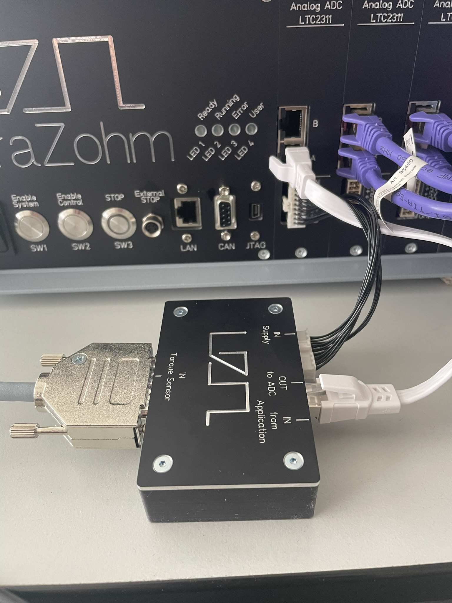
After the assembly, the PCB can be connected to the UZ, e.g., to a lot A from ADC A1, as shown in the picture below.
Downloads#
Designer#
Designed by Michael Hoerner (TH Nürnberg), 07/2024