Switches and Jumpers#
Motivation
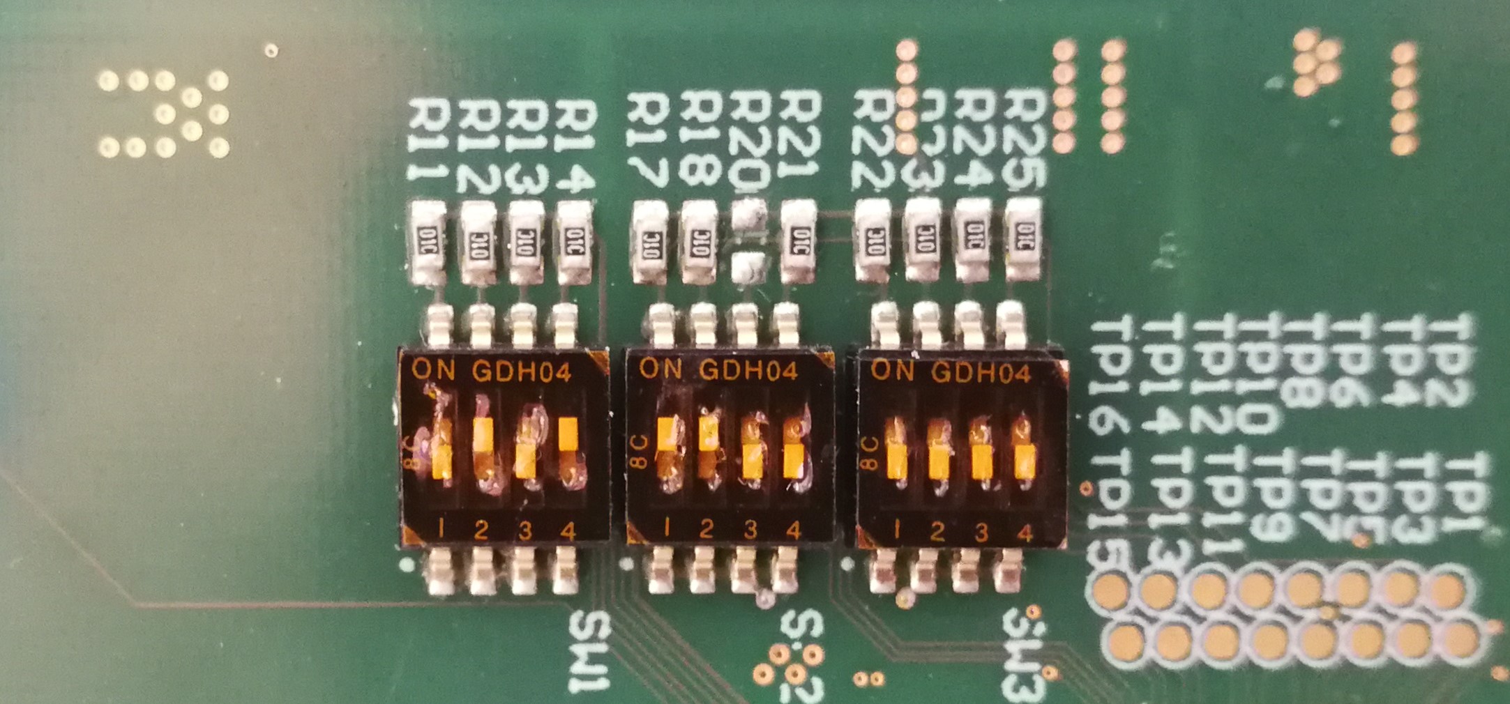
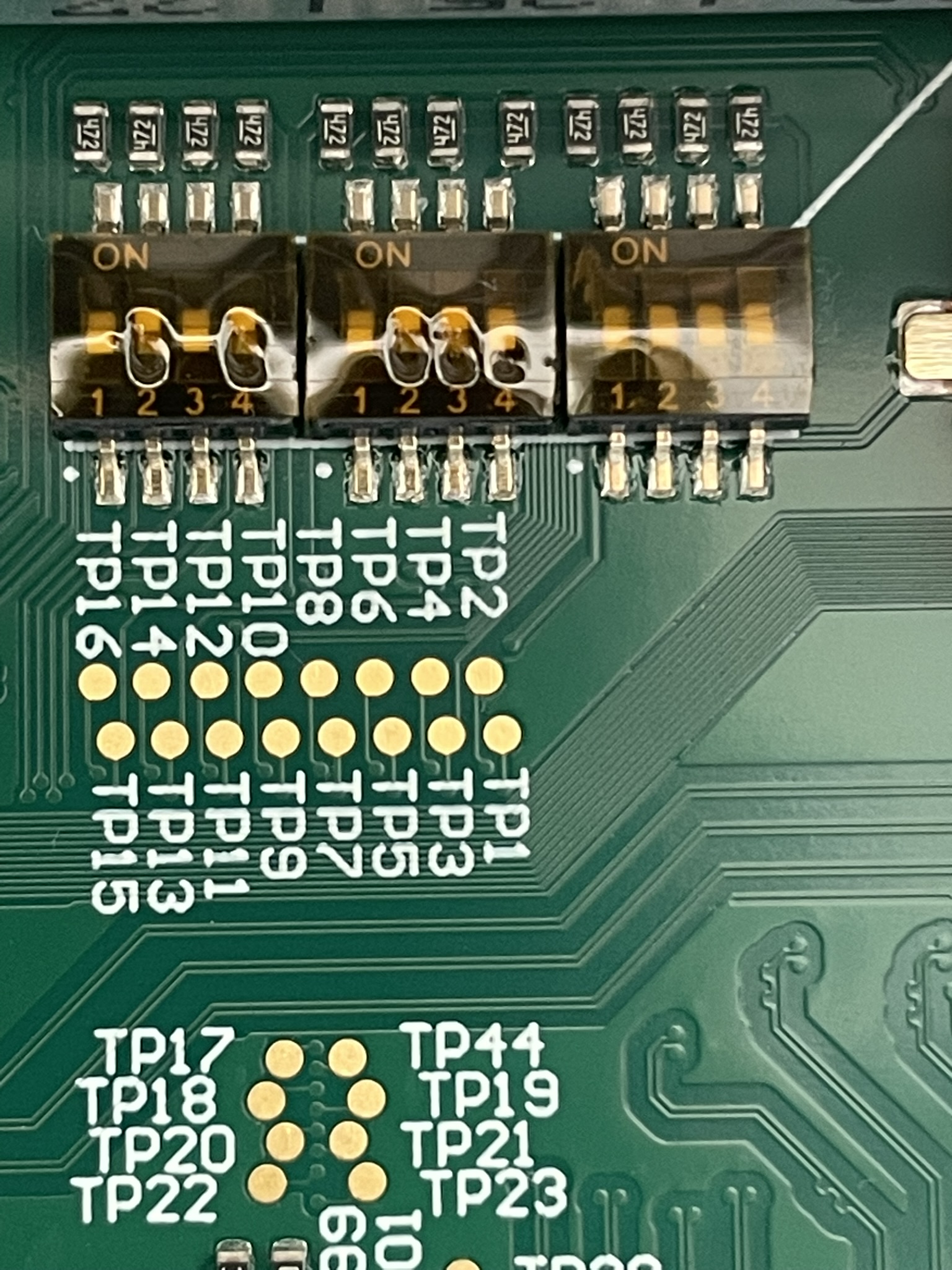
The carrier board has several DIP switches on the back to change the boot mode and to activate or deactivate the power supply for various functions. The settings of the switches are chosen regarding the “TRM-TEBT0808-01” manual.
SW1 - Boot Mode#
Adjustments for booting (Boot Mode Settings -> page 7 of TRM-TEBT0808.01):
The
default configurationfor the UltraZohm is to useSD1.
SW1-1 |
SW1-2 |
SW1-3 |
SW1-4 |
Bootmode Hex |
Bootmode |
Comment |
|---|---|---|---|---|---|---|
M0 |
M1 |
M2 |
M3 |
|||
ON |
ON |
ON |
ON |
0x0 |
PS Main JTAG (TE0790 USB JTAG) |
Needed for SPI Flash Programming |
ON |
OFF |
ON |
ON |
0x2 |
SPI Flash (dual parallel, 4bit x 2, 32bit Addressing) |
Default |
0x3 |
SD0: Supports SD 2.0. |
MIO[25:13] |
||||
|
|
|
|
0x5 |
SD1: Supports SD 2.0. |
MIO[51:38] |
A more detailed description is given in Table 9 of <https://wiki.trenz-electronic.de/display/PD/TE0808+TRM>
SW2 - Power Mode First Part#
EN_GT is disabled, because of a Bug in the layout for “EN_GT_L” -> Anyway, this is for FireFly and not necessary so far.
The
default configurationfor the UltraZohm ishighlighted.
Power Mode |
SW2-1 |
SW2-2 |
SW2-3 |
SW2-4 |
|---|---|---|---|---|
EN_PSGT |
EN_GT_R |
EN_GT_L |
EN_PLL_PWR |
|
Power/Rail Disabled |
|
|
ON |
ON |
Power/Rail Enabled |
OFF |
OFF |
|
|
SW3 - Power Mode Second Part#
All switches are changed to “Off” in order to send 3.3V to the Enable Pins and switch on the respective DC/DC converters on the Trenz module.
The
default configurationfor the UltraZohm ishighlighted.
Power Mode |
SW3-1 |
SW3-2 |
SW3-3 |
SW3-4 |
|---|---|---|---|---|
EN_DDR |
EN_LPD |
EN_PL |
EN_FPD |
|
Power/Rail Disabled |
ON |
ON |
ON |
ON |
Power/Rail Enabled |
|
|
|
|
Default adjustments for the UltraZohm ≤Rev04#
Default adjustments for the UltraZohm ≥Rev05#
See also: