When creating a schematic in Altium, there are many different ways to place components and use their footprints for the layout. In a project for the UltraZohm the UltraZohm component library is used exclusively.
If the required components are not available in the current library status they must be added. Newly added components must fulfill the following requirements:
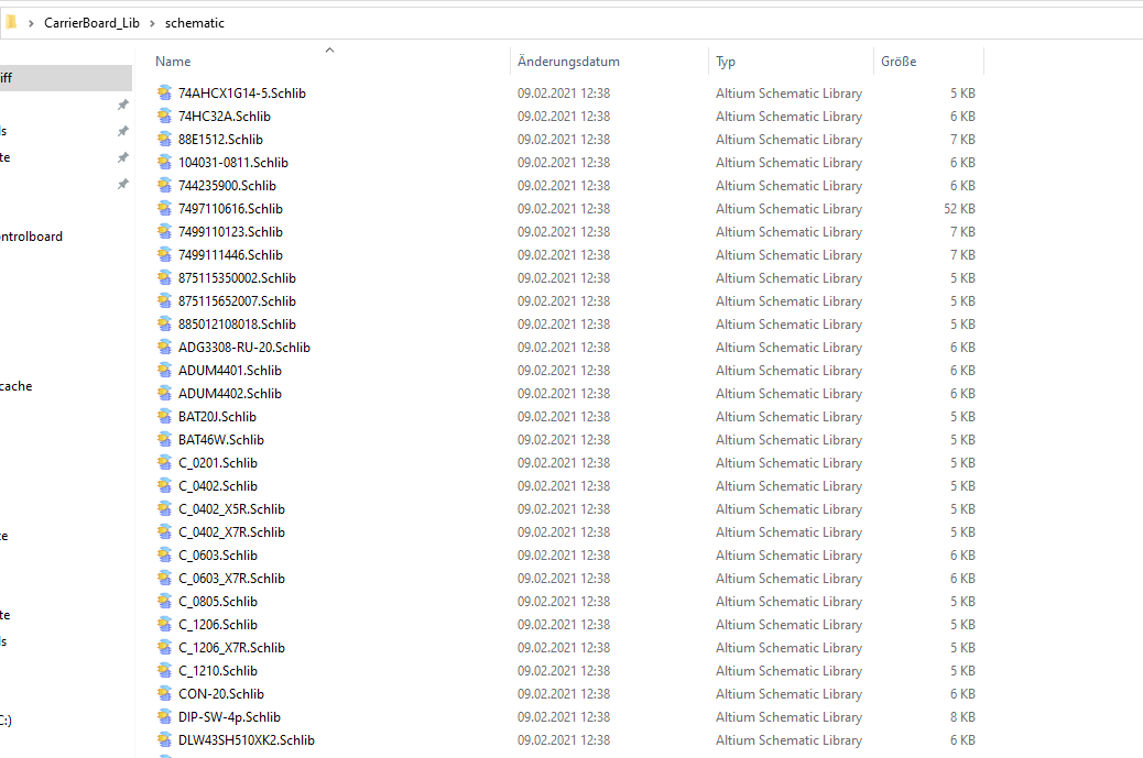
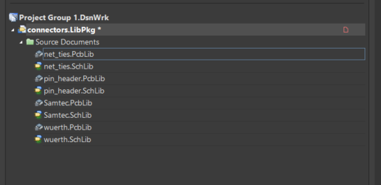
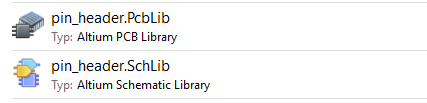
A .SchLib or .PcbLib file must contain only a single symbol or footprint. If this requirement is not fulfilled it is impossible to resolve merge conflicts when people are working on the library
The footprint must follow the mapping of the mechanical layers. This is vital in order to generate high quality documentation and production output. The requirements can be found under Mapping of the mechanical layers
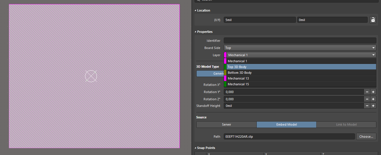
If the manufacturer supplies a 3D model of the component it must be included to the footprint.
If the user detects a footprint that does not follow the requirements mentioned above he is strongly encouraged to update the component or to open an issue and assign it to the maintainer (i.e. creator) of the component.
In the following, 4 different ways will be presented, how to create the appropriate schematic and footprint format for the Altium DB Library used in the UltraZohm project:
If both the schematic as well as the footprint are available from the manufacturer for Altium in separate files and if these files only contain one symbol or footprint you can start directly by integrating these components into the library.
Please be aware that you will have to adjust the mechanical layers in the footprint. See UltraZohm components library for further instructions. If the desired component is combined in a library with several other components, see the following sections.
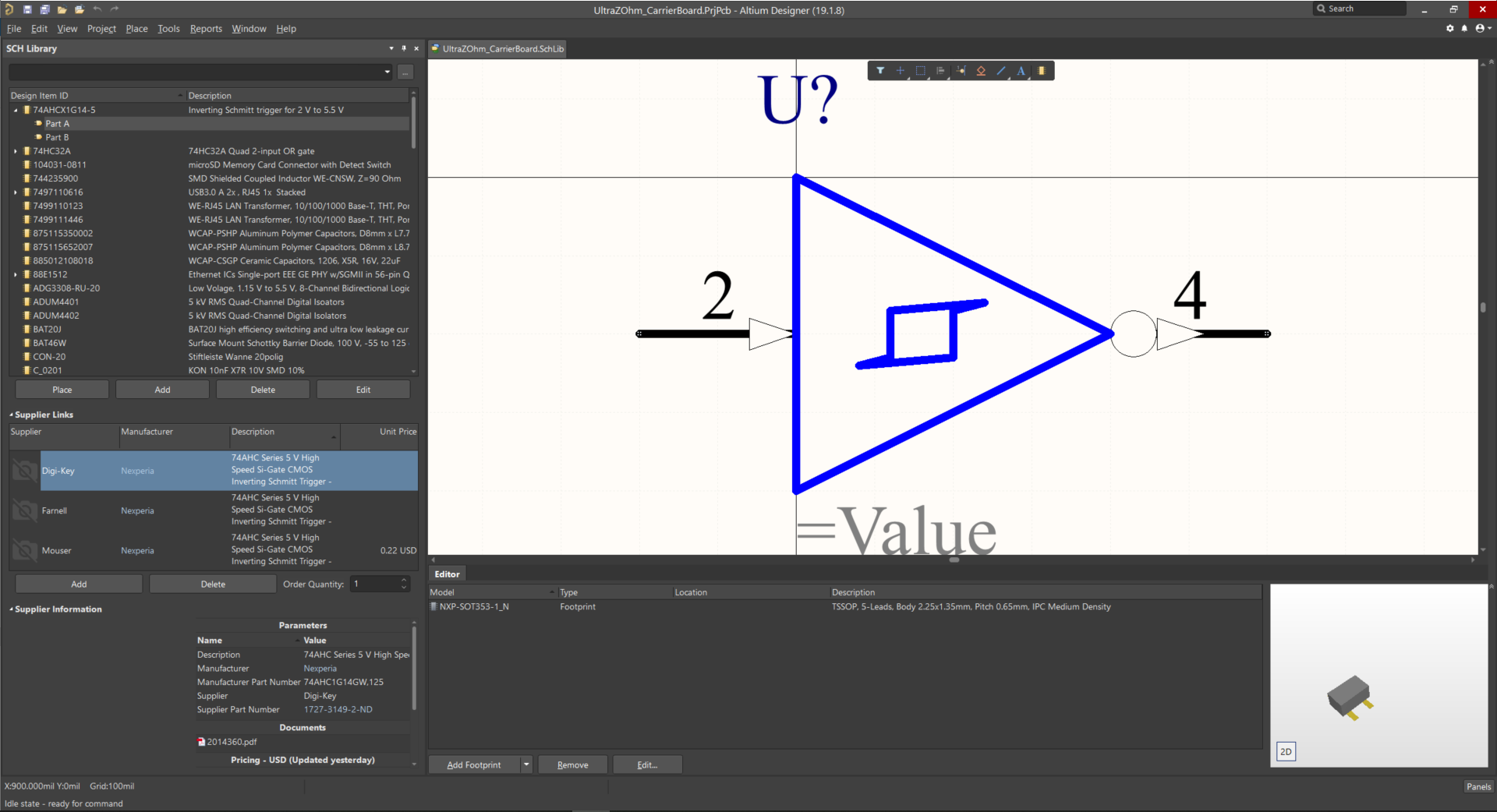
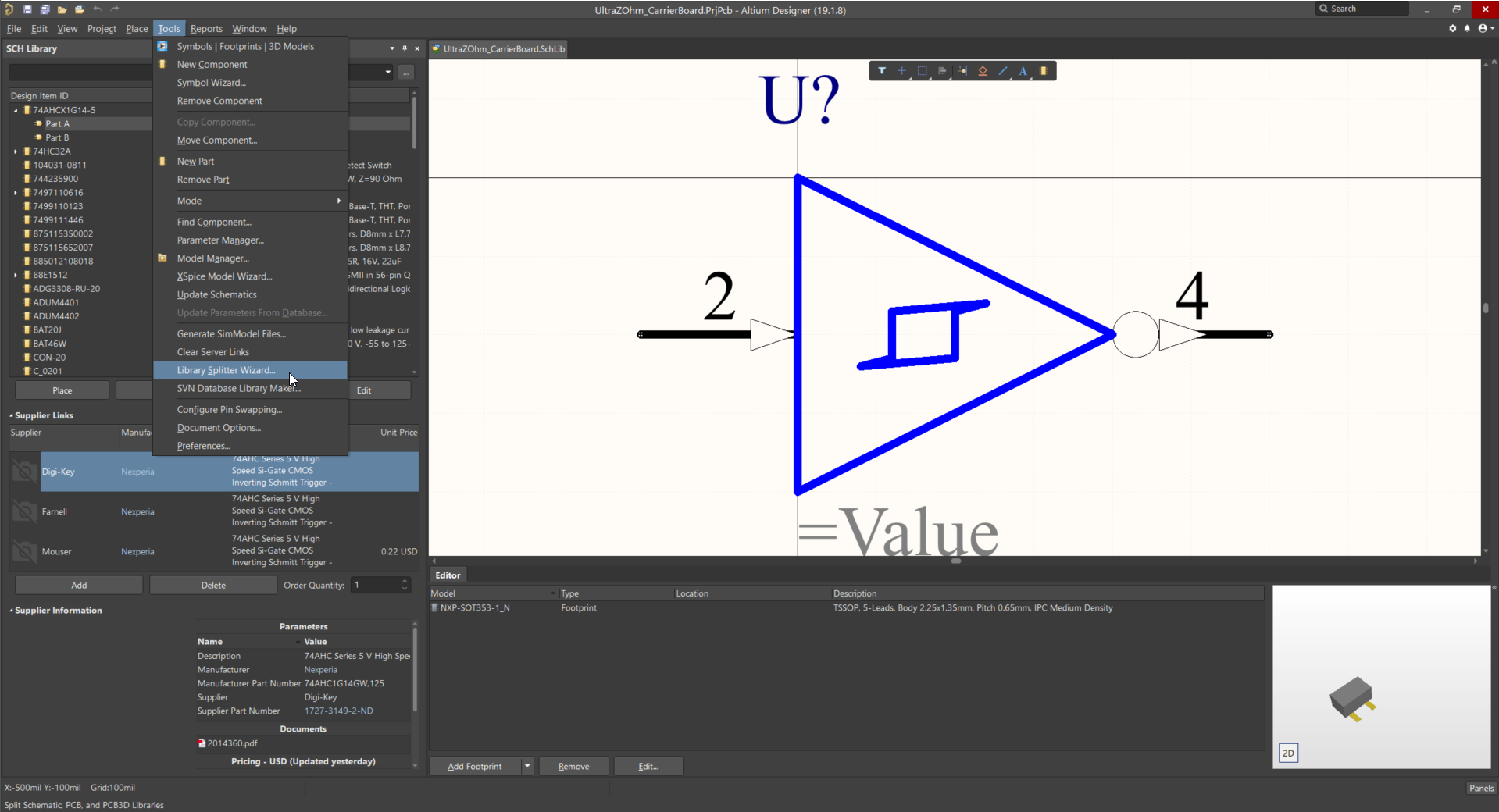
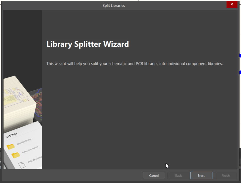
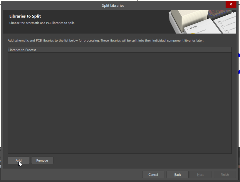
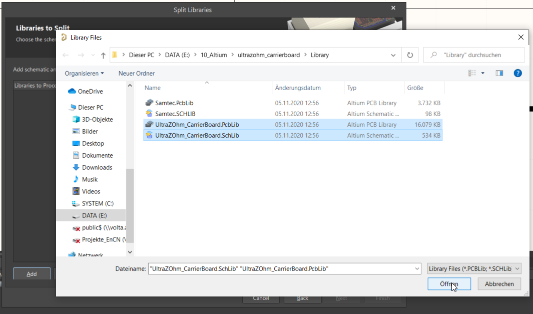
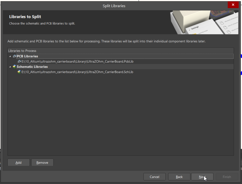
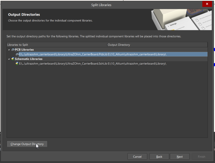
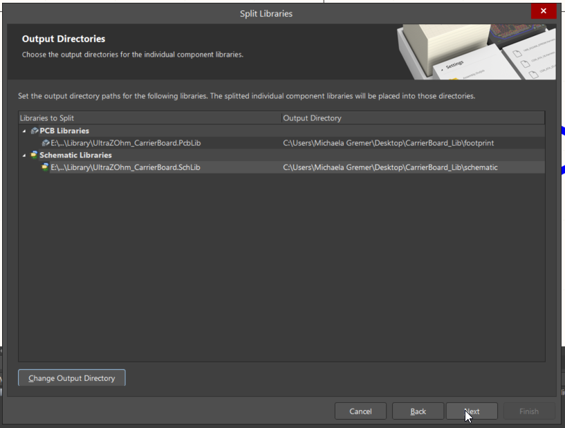
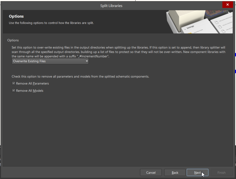
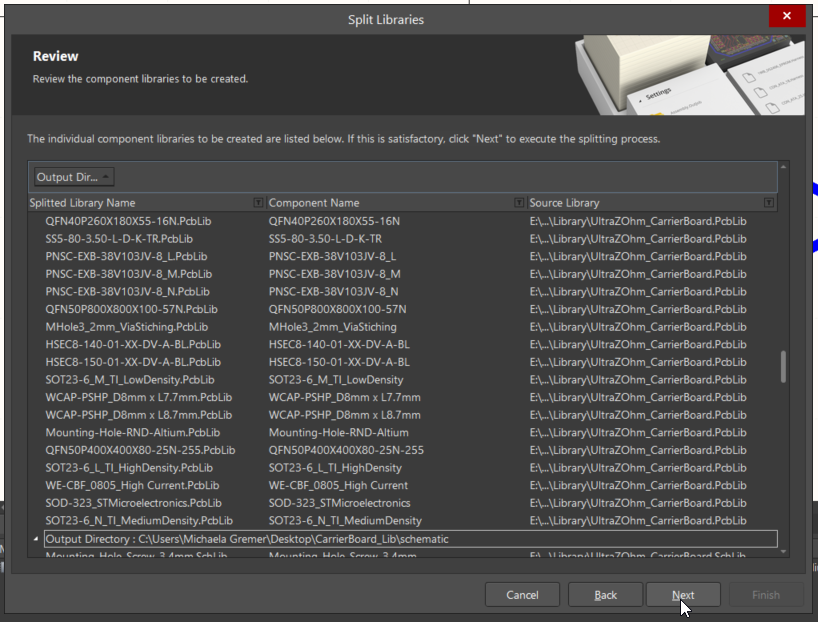
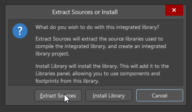
If a component is in a library file (.SchLib or .PcbLib) with several other components this component must be separated from the other components in the schematic symbol library as well as in the footprint library.
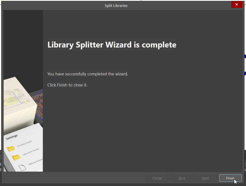
Altium provides the LibrarySplitterWizard for this purpose so no manual extraction is required.
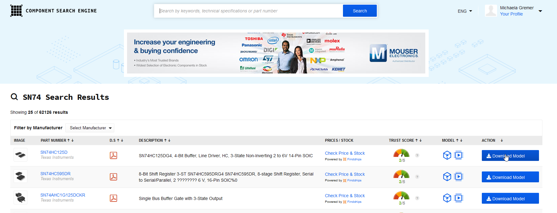
Sometimes, there are no symbols or footprints directly from the manufacturer available.
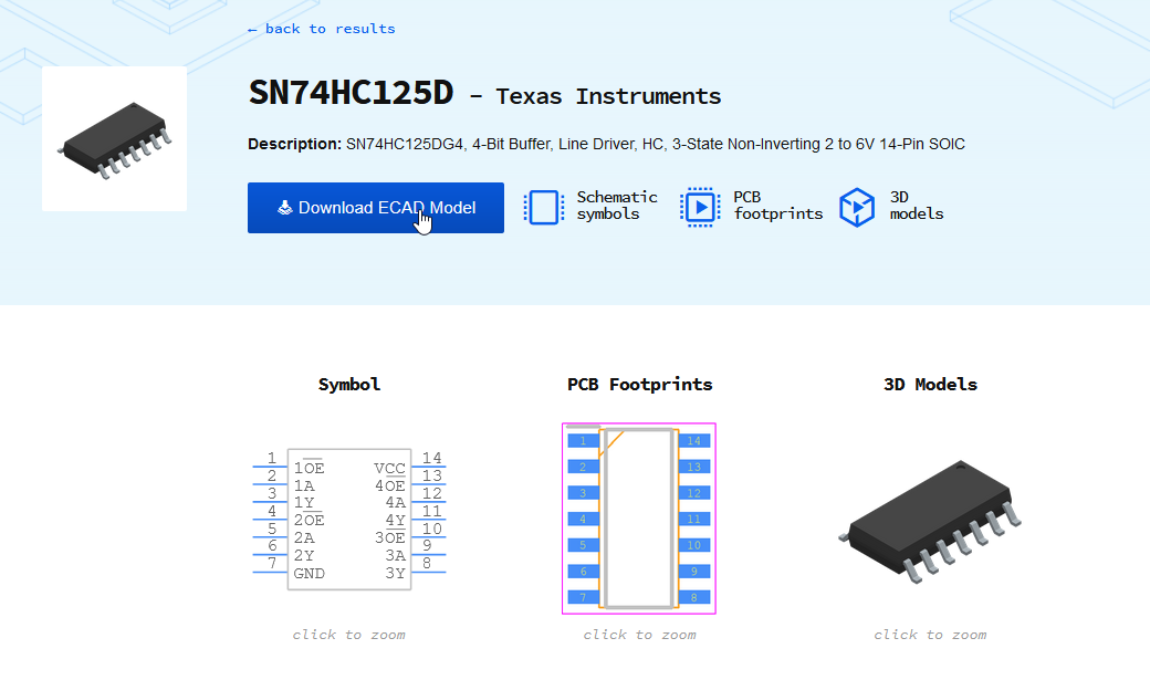
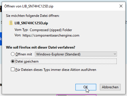
Then you can use the component search engine (https://componentsearchengine.com/logPartRequest.php), where you can access a large number of already existing components or request new models for Altium.
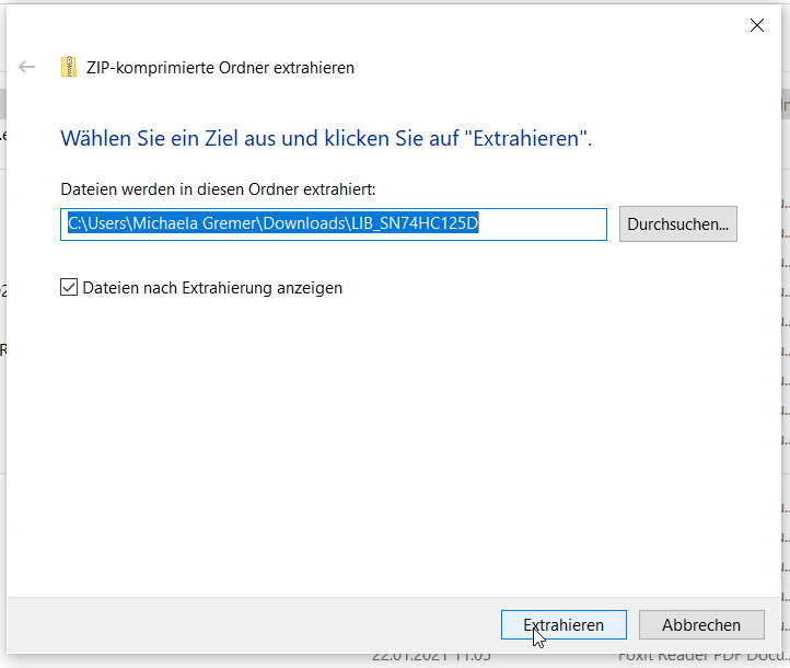
To enter these components into the database, proceed as follows:
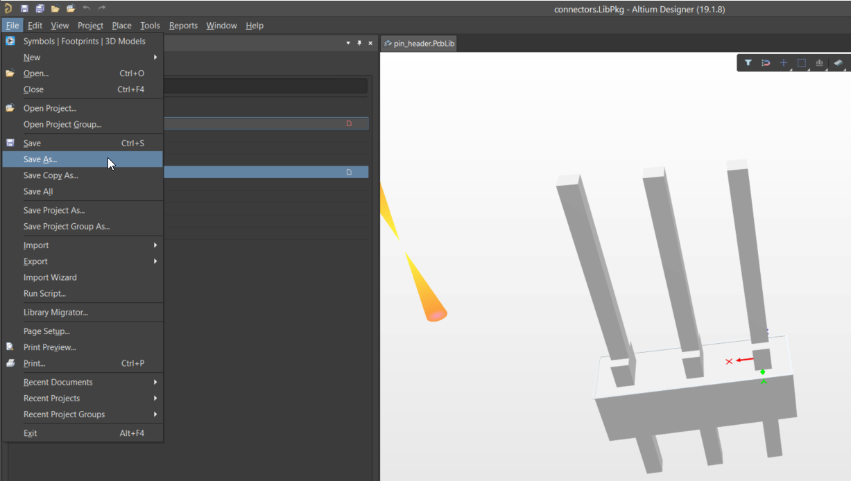
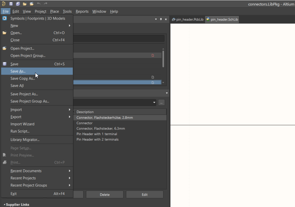
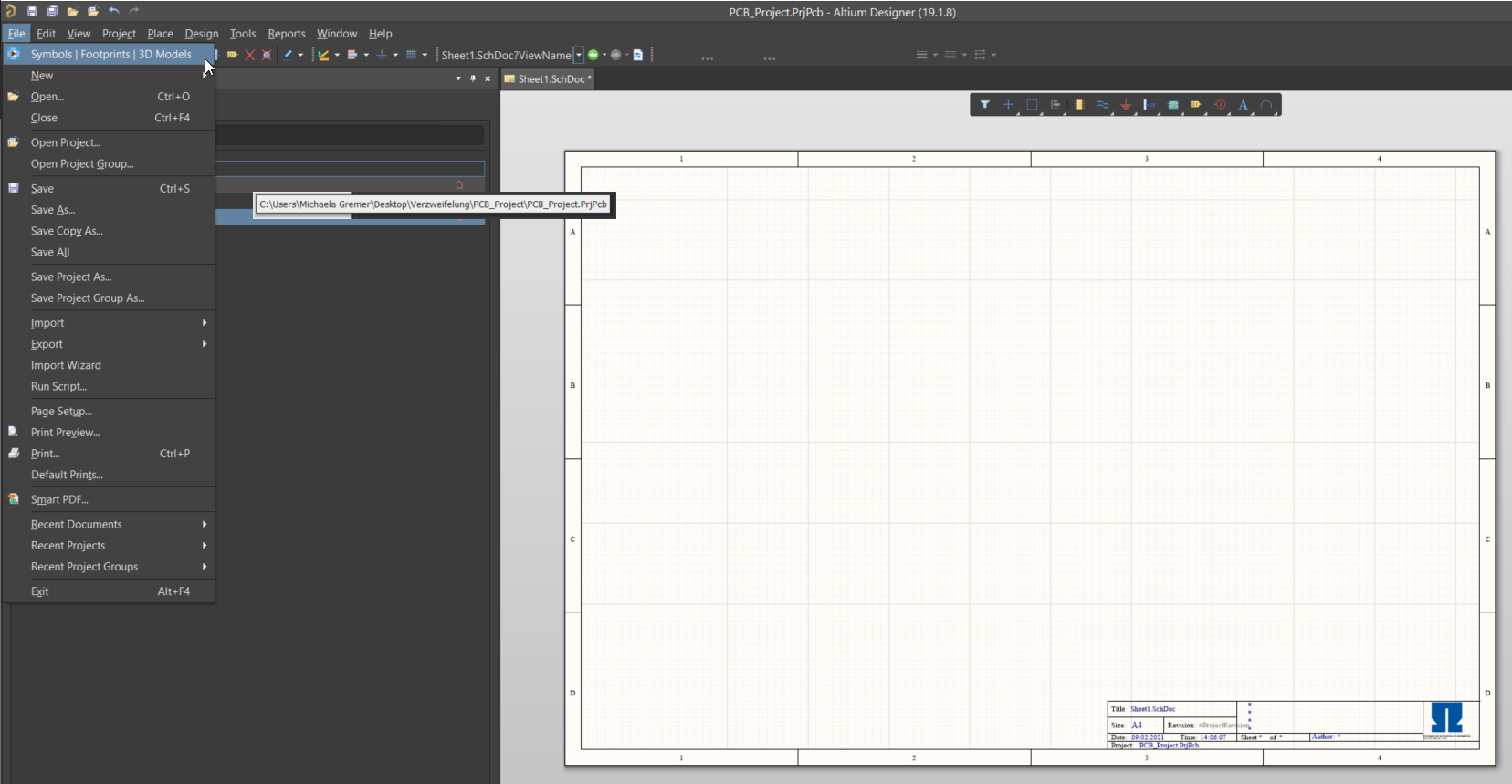
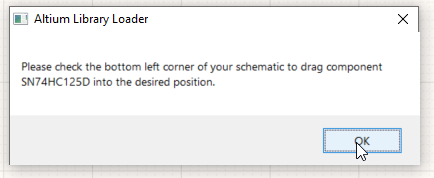
5. Open Altium and a schematic file before the Altium Loader will be opened by selecting File –> SymbolsFootprints3DModels
(If this tab does not exist, the necessary plug in is missing.
Therefore read and install the Altium Library Loader https://www.samacsys.com/altium-designer-library-instructions/)
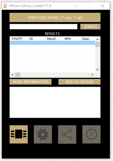
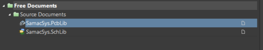
At this point, the SamacSys lib can be reused or the respective symbols with the corresponding footprint can be stored in a temporary lib.
Afterwards you have to continue with the instructions: More than one symbol or footprint in one file
When creating a component several layers types can be defined. Besides the standard layers like Top and Bottom copper overlay etc. mechanical layers can be defined.
These layers carry information for the generated documentation output. In order to be able to reuse a certain output job to generate the documentation and production output
the mechanical layers must follow a uniform mapping. The mapping is distinguished in two different categories:
Table 72 shows the mapping of the component layer pairs to the functions. Even if Altium can handle the numbering of the layers automatically when assigning component layer pairs
in the UltraZohm library only components that follow this layer mapping are accepted. The mapping of the additional mechanical layers from Table 73 must be considered especially
in the PCB design when putting certain meta information in the layout.
Unfortunately, the footprints that can be obtained from the manufacturer usually do not follow the mapping from the table above.
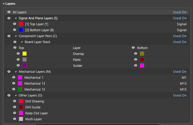
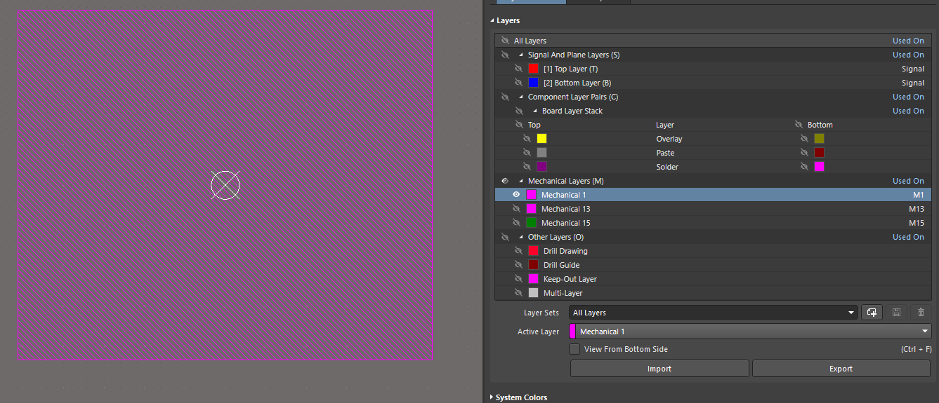
Fig. 190 shows a typical mechanical layer stackup when a component is freshly downloaded from the manufacturer homepage.
Fig. 190 Typical layer stack in AD before editing#
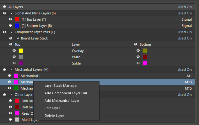
In order to adapt those components to the required layer mapping there are two ways of editing your new library part:
Loading the stackup template file from the UltraZohm Altium Library
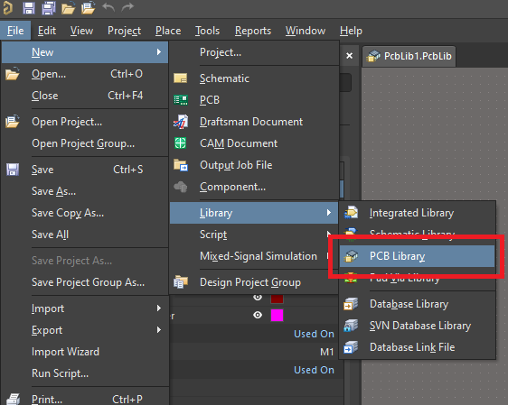
Create a new PCB Library in Altium altium-designer
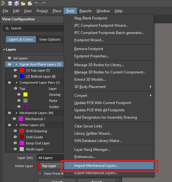
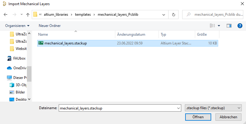
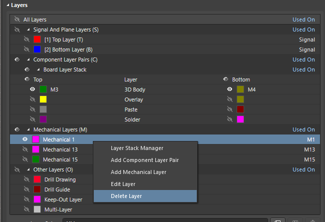
Import the predefined mechanical layer stackup file that is located in the Altium Library Repository under ..\altium_libraries\templates\mechanical_layers_Pcblib
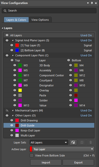
After successful loading of the mechanical layer stackup template file your layer set should look like following