Assembly#
Below, the assembly instructions for the setting up the connection between UZ and the Deskbench are explained in detail.
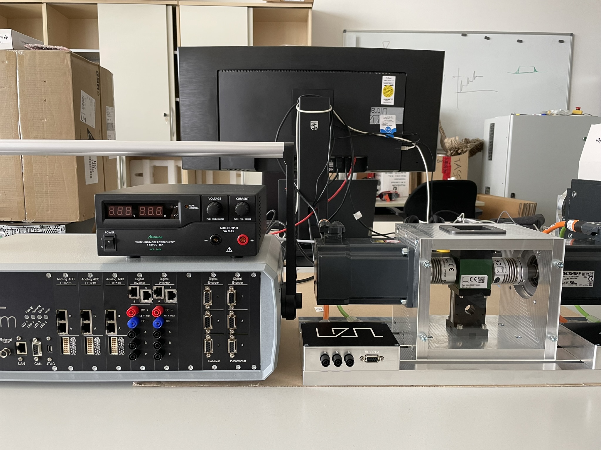
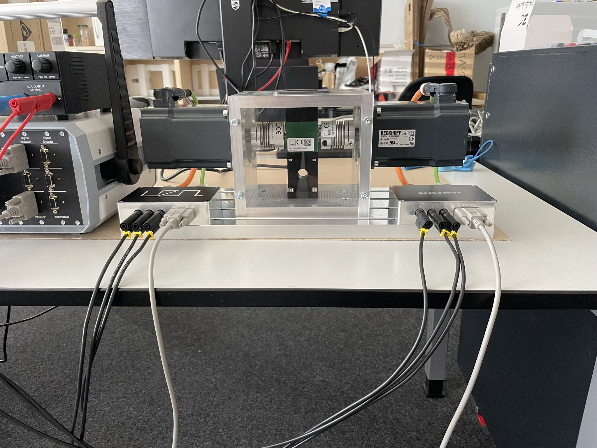
Setup the UltraZohm, the power supply and the deskbench for your needs.
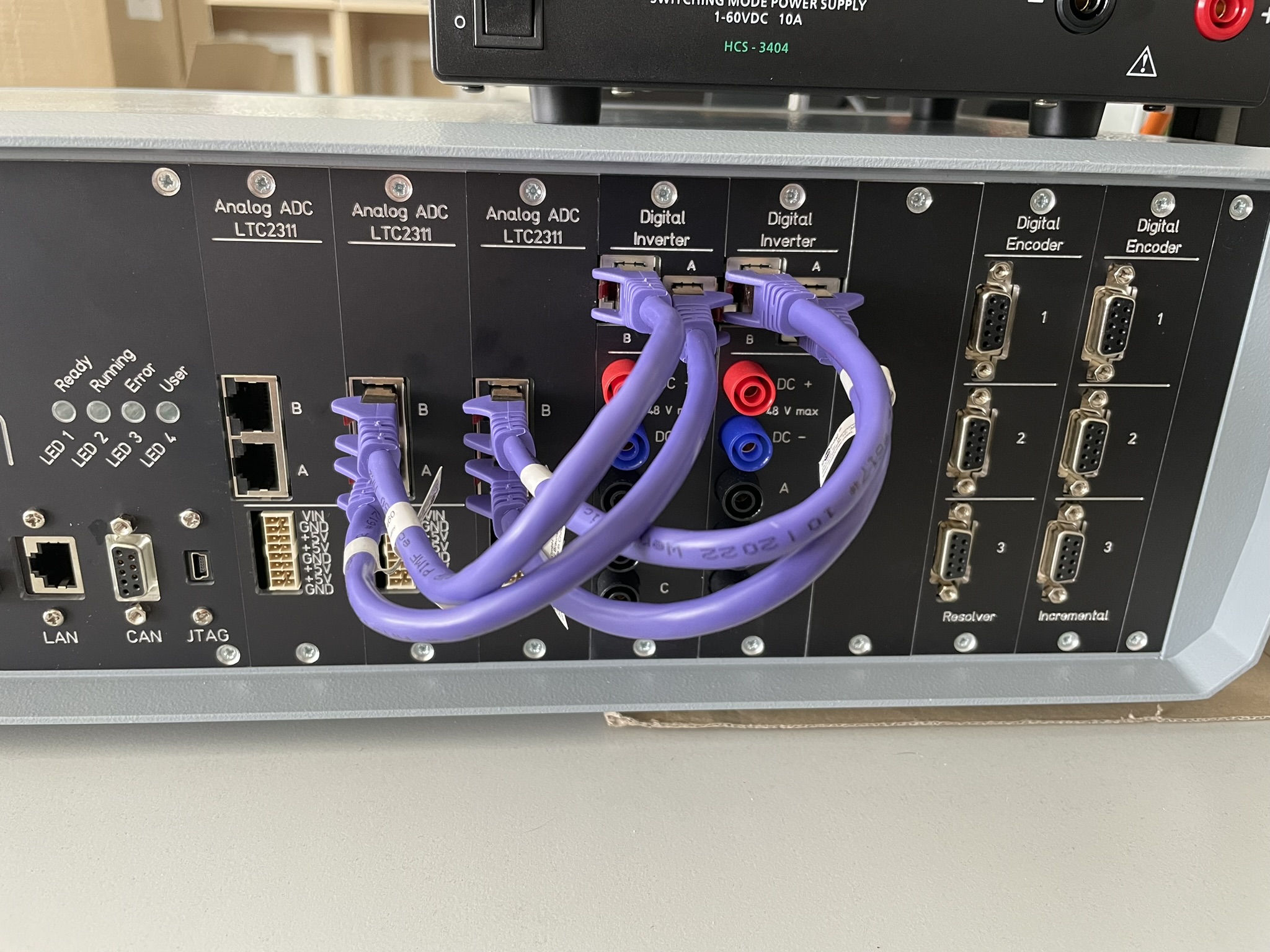
Connect the two Inverters to the ADC Cards.
Port Inverter |
ADC Card Port |
|---|---|
D1 A |
ADC A2 A |
D1 B |
ADC A2 B |
D2 A |
ADC A3 A |
D2 B |
ADC A3 B |
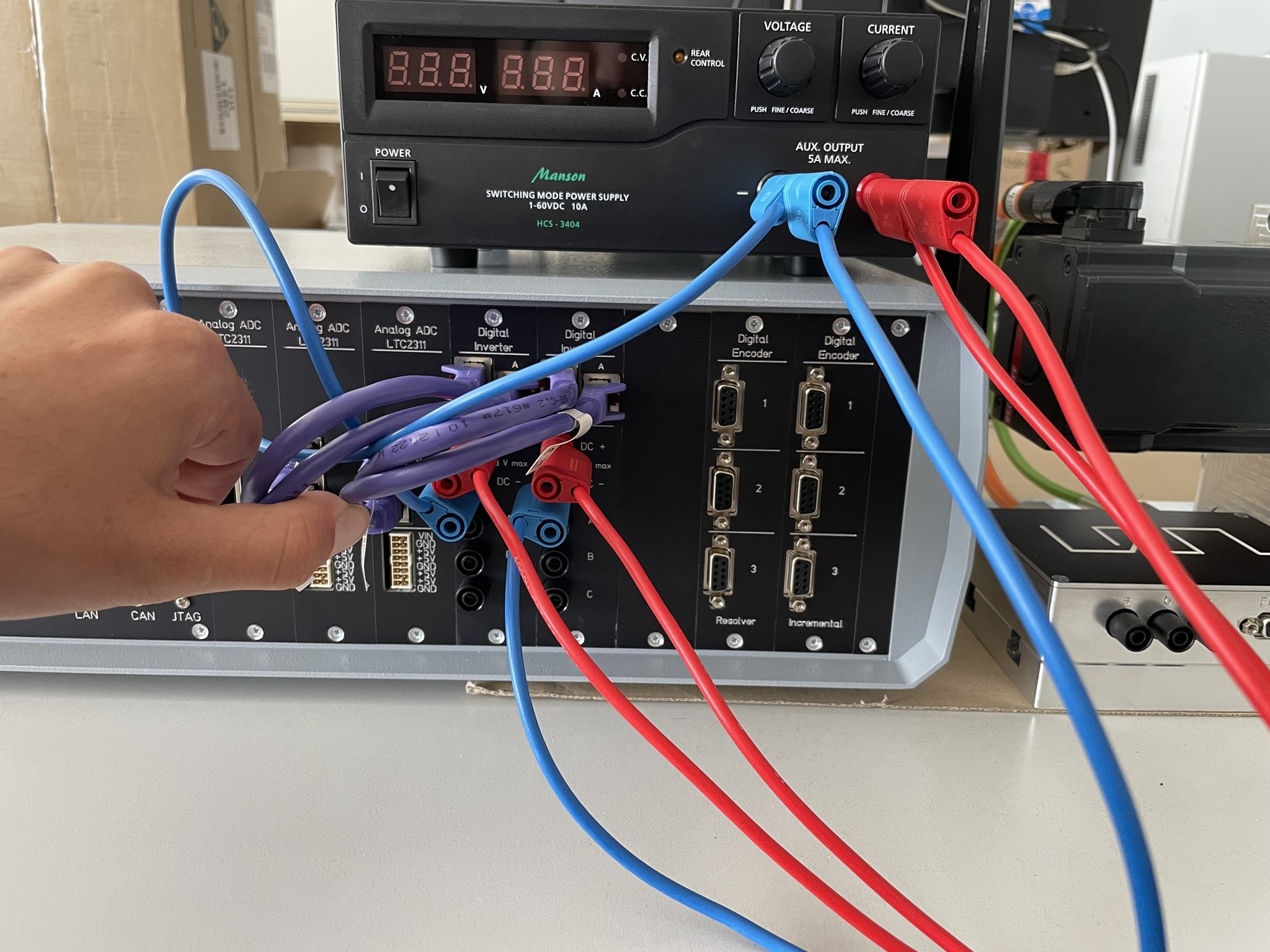
Connect DC+ and DC- to both inverters on D1 and D2 with lab cables. Ensure that the current carrying capability of the cables is sufficient!
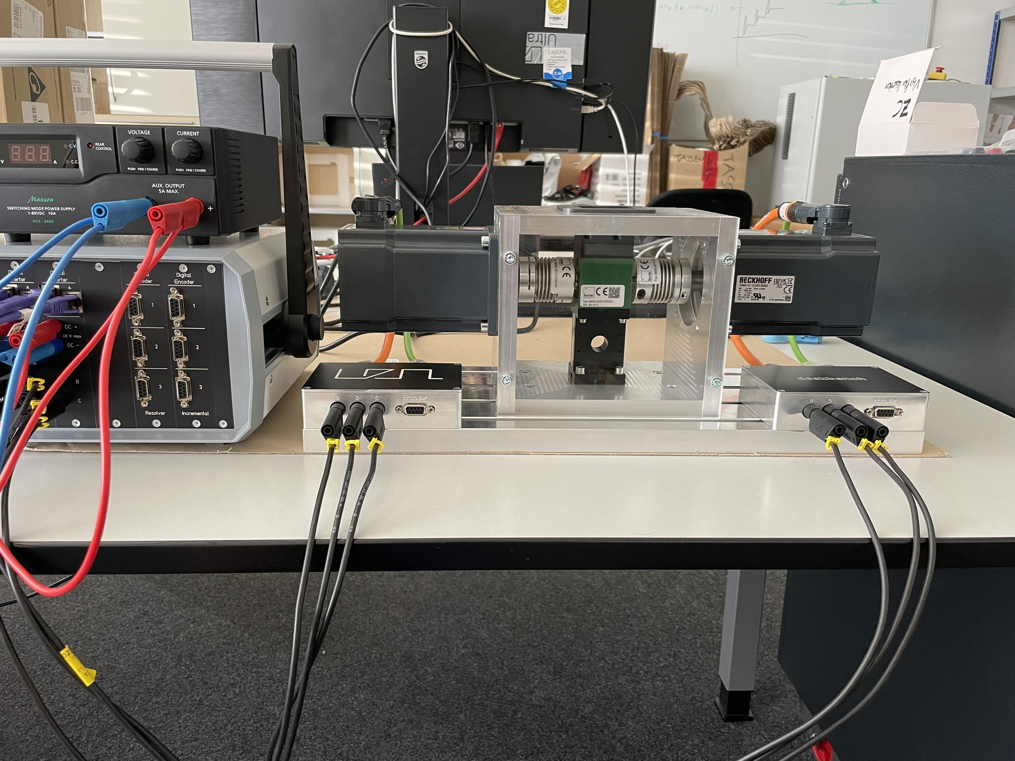
Connect Phase A-C of both inverters to the Deskbench terminal boxes. Ensure that the current carrying capability of the cables is sufficient!
Connect the two Resolver to the UltraZohm with the D-SUB 9 Cables. Ensure that the cable is a “straight through” cable with one to one connection of the pins!
Motor 1 (left) |
Motor 2 (right) |
|---|---|
Phase A => D1 A |
Phase A => D2 A |
Phase B => D1 B |
Phase B => D2 B |
Phase C => D1 C |
Phase C => D2 C |
Resolver => D4 1 |
Resolver => D4 3 |
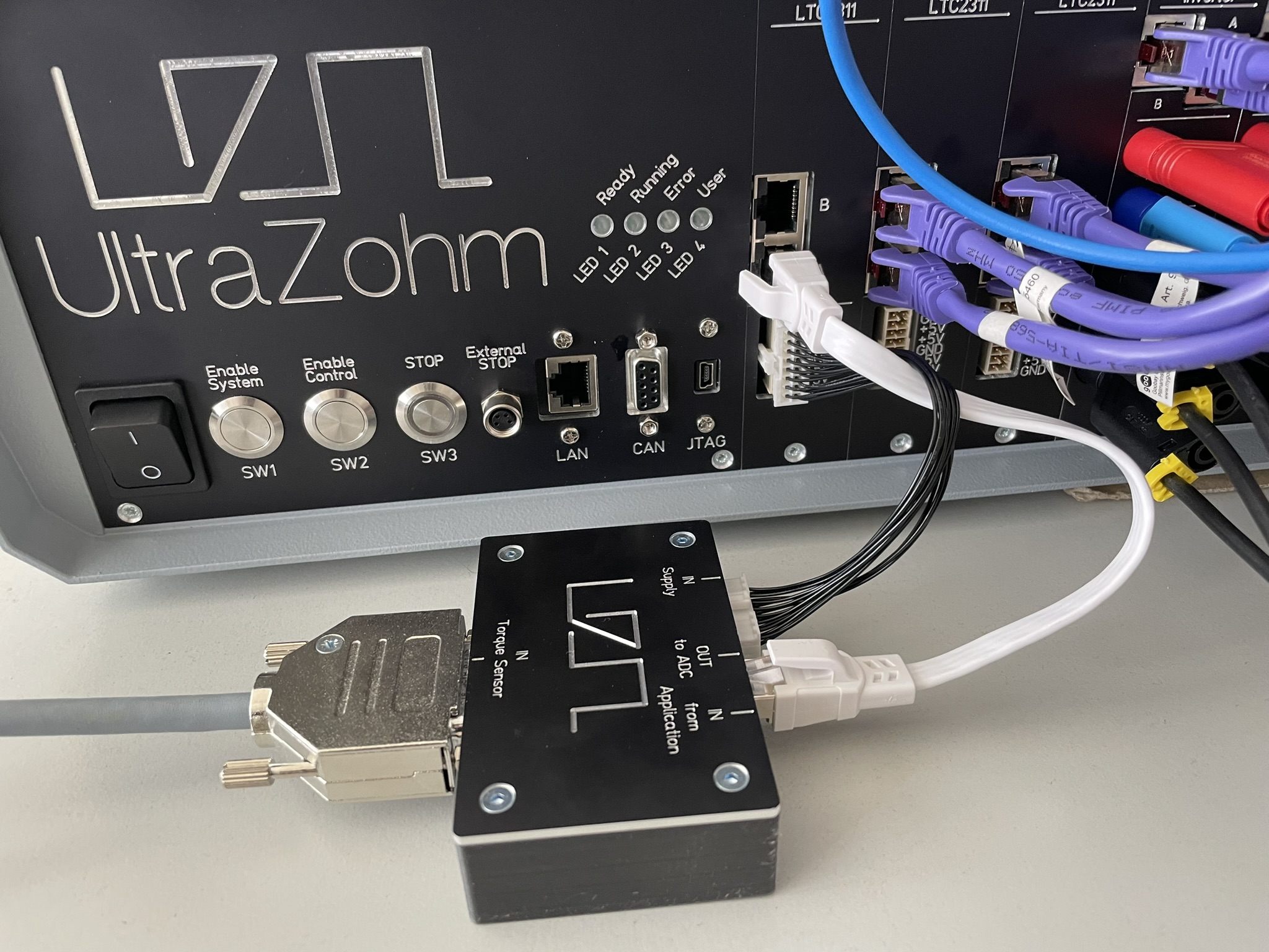
6. Connect the OUT to ADC connector from the Torque Box PCB to A1 A with a RJ45 cable.
Connect the Supply IN connector of the box with the ADC A1 supply connector, using the delivered Samtec cable MMSD-08-28-F-xx.xx-D-K-LDX.
Connect the torque sensor D-SUB 15 cable with the Torque Box PCB IN Torque Sensor connector.
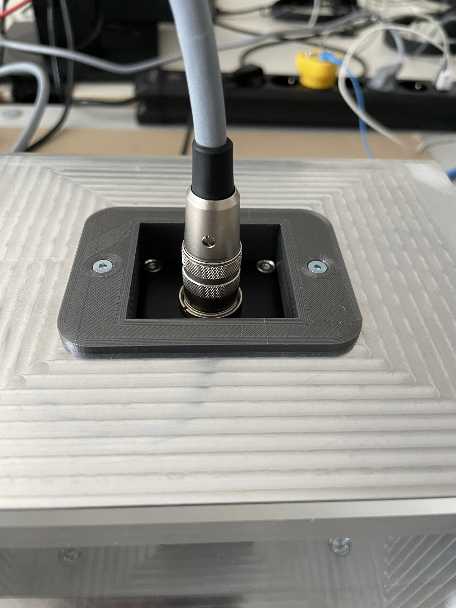
Connect the torque sensor cable with the torque sensor of the deskbench.
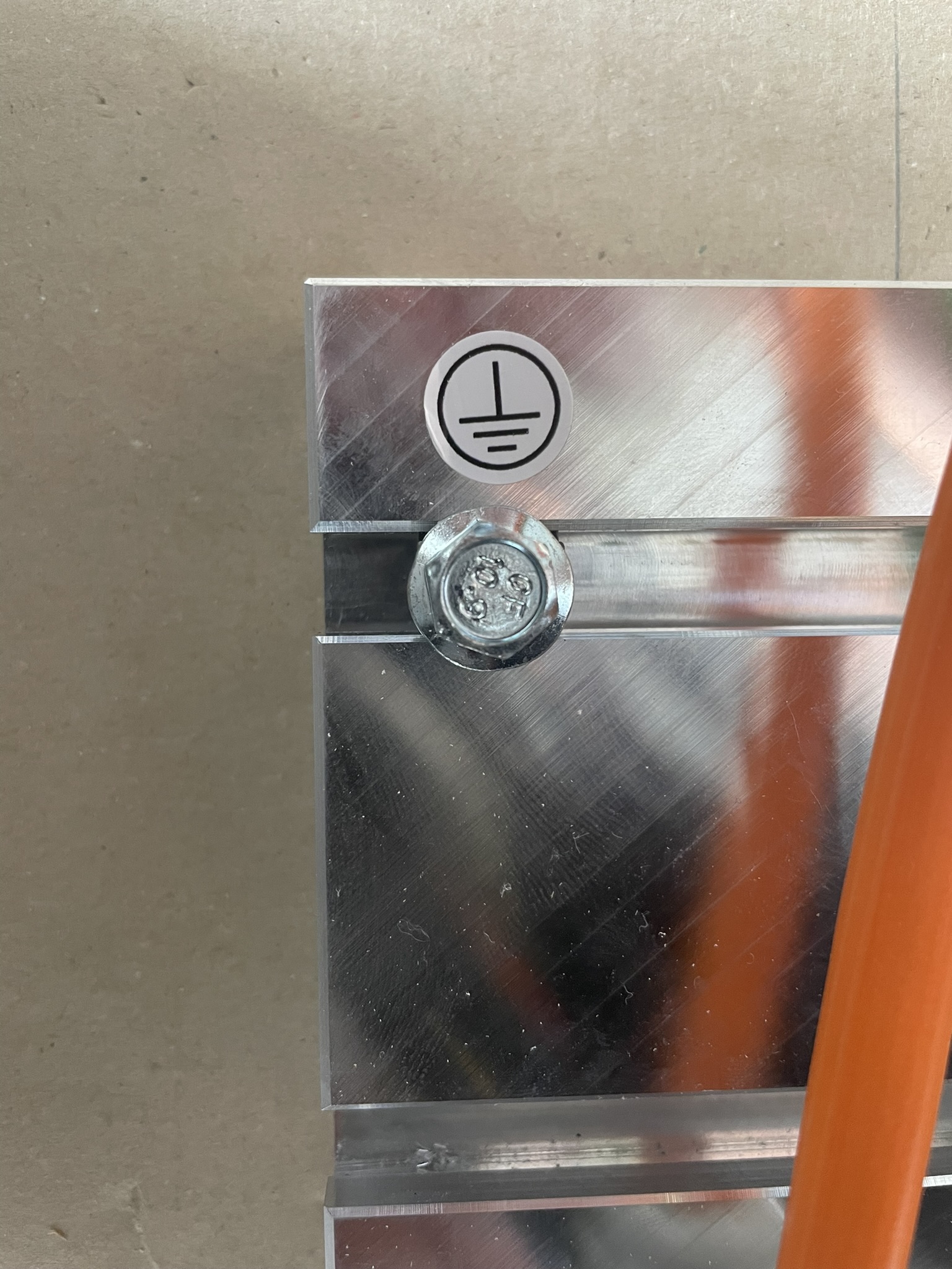
Make sure that the deskbench is properly grounded. There is a fastener for the connection to ground in the top left-hand corner.
Connect the UltraZohm to your host computer.
The physical and electrical connections have been successfully completed. The next step is to setup the Software implementation.