Overview#
These pages document the next-generation (i.e., “post-Rev04”) revision of the UltraZohm carrier and its associated components (front panel, housing, etc.). Among various on-board changes, this revision of the carrier board replaces the previously wire-connected front panel with a PCB-based solution (cf. Hardware and Comparison of front panels across carrier board revisions (photos) for an overview, and Frontpanel Mainboard (Rev01) for details).
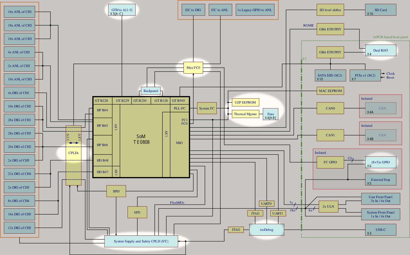
An overview about the interfaces of pre-Rev04 systems is shown in chapter Overview, whilst the additions of Rev04 are documented here.
“What’s different?” for Rev04 Users#
Power-on/off: As long as the power switch on the backpanel is on, the UltraZohm can be
switched on by briefly pushing the “Power” button on the frontpanel, and
switched off by holding the “Power” button for (at least) 2 seconds.
Ethernet: Connect your PC running the Javascope to “LAN 0” on the frontpanel
The STOP and Enable buttons on the frontpanel now have an effect beyond the UZ software as they cause state transitions in the Statemachine for S3C - Please refer to Powerbutton Functionality for caveats if both the frontpanel buttons and the Javascope GUI are used at the same time
Note that the 24V rails sent to the adapter cards are now e-fused; if an overcurrent occurs, the rail of the affected card is disabled and remains so until a powercycle
The D-slot CPLDs no longer are programmed via a dedicated debug module and, thus, USB cable; instead, SoM and CPLD JTAGs are integrated, which enables CPLD programming via their dedicated channel (see IsoJTAG_Adapter regarding a retrofit option for Rev04 and older systems)
Hints for Operation and Troubleshooting#
The Power button’s color indicates the system status as follows
Blue: System is (soft-)powered off - In longer periods of stand-by, it is recommended to fully disconnect the system from mains (by means of the backpanel switch)
Green: System is powered on and operates as known from previous system/carrier revisions
Blue: Warning (currently unused)
Red: Hard (i.e., un-resettable) error - Push the Power button on the frontpanel to acknowledge the error (and to prepare for a later power on the system)
White: Soft (i.e., recoverable) error - Press “Enable System” on the frontpanel to return to regular operation
Cyan, magenta, white and yellow (also) serve as indicators during state transitions
There now are three (physical) fuses, one in the 230V assembly on the backpanel and two (F1/F2) on the carrier itself (top right-hand corner)
The UltraZohm now incorporates a system-level management component, the “S3C”, as introduced below - Please refer to System Supply & Safety Component (S3C) for more information and feature extensions
Summary of new Features and Changes#
Integration of a System Supply and Safety CPLD/Controller (“S3C”) that
monitors the various system parameters (e.g., supply voltage, power good signals and thermal status),
drives a “carrier ready” signal to the adapter cards (based thereon),
monitors status signals from the adapter cards (and, in case of D[1-5], also their slot-local CPLD),
conditionally forwards per-D-slot output-enable signals from the slot-local CPLD to its associated adapter card whilst A slots are connected directly (cf. the pin formerly used for
PILOT_OUT),drives and/or receives the twelve digital adapter card signals of slot D5 previously not connected, and
routes various PS-MIOs and up to six PL pins to wherever they are needed (e.g., on slot D5 or FP).
See System Supply & Safety Component (S3C) for details of the used part, its supply, and the already implemented and prospective functions
Reassignment of various PS-MIOs to enable new functions & bug fixes (see itemized list of MIO-related changes for details and software compatibility)
New, more flexible “CPLDs” (now de facto FPGAs) on the five D slots
Larger fabric size of 2112 LUTs (compared to the 128/256 macrocells of the Lx4128/LC4256V on pre-Rev05 carriers)
Integrated I²C and SPI controllers for communication and (in addition to traditional JTAG) programming of fabric, feature row and internal Flash
Integrated PLL, 16-bit timer (with PWM and CC support) and user-accessible Flash memory for configuration data etc.
No external/shared clock supplied by the carrier, the local oscillator has to be used on a per-slot basis
Isolated JTAG+UART interface to avoid ground loops during debugging
Dual-JTAG to program both SoM and D-slot CPLDs using a single cable
Dual-UART (from SoM to USB) for independent consoles of RPU and APU
SysMon-based monitoring of VIN for application-specific error logic
Per-slot current limit on VIN (with error signaling to S3C / CPLDs)
New, fully PCB-based front panel (FP) with
added Second Gigabit Ethernet interface (via SGMII)
added 15-pin D-sub connector with 8+5 Isolated I/Os (“isoIOs”) for
up to 12 software-controlled general-purpose I/Os (GPIOs),
up to 4 hardware-controllable GPIOs from/to S3C (and PL),
one dedicated hardware-controlled GPO for a heartbeat, and
an external output of the integrated isolated 3V3 supply.
improved isolated “External STOP” connector, where
the (normally-closed) signal now not only is sent to the PS but also can be routed to all the hardware-programmable devices (i.e., the CPLDs of the D slots and the PL) via the S3C, and
two optional software-controllable GPIOs are available.
the four serial multi-Gigabit/s transceivers of the PS (“PS-GTR”s) now being fully accessible and, as of Rev01 of the FP, used for the
second Gigabit Ethernet (as in Rev04, but now on the FP), an
internal M.2 slot for a 6 Gbit/s SATA-2 SSD, and an
internal M.2 slot for a single-lane PCIe (v2.0) EP.
The fourth PS-GTR lane (pair) is currently not assigned but available on the FP connector for future extensions
Details, features and differences of Rev01- and Rev02-based FPs can be found on their respective pages
Breakout of three GTH quads (x1 to each A slot, x1 to FP, and x4 to BPs) and of one dedicated differential PLL clock per A slot and SoM clock per BP
Integrated thermal management for
configuration-free temperature-driven control of up to two fans, and
monitoring of fan status, SoM temperature and system temperature
All shared signals between SoM (both PS and PL) and the adapter card slots have been removed, with the only exception being a per-group I²C bus and an ANL_Pin54_Legacy signal to maintain compatibility as already targeted by Rev04 (cf. last bullet point in Short summary of new features of Rev04)
Migration of the SoM I²C (with its PLL and, in newer revisions, an EEPROM) from PS I²C0 to I²C1
Separation of the User I²C (PS I²C0) using an 8-channel bus switch linking to FP (for the isoIOs), A slots, D slot CPLDs, D slots, secondary S3C I²C, and BPs (cf. I²C on ≥Rev05 carriers for details)
Support for identification of adapter cards (in line with the corresponding retrofit for Rev04)
Integrated identification EEPROM used by the UZ platform framework with associated circuitry (in line with the I²C/SSD/S²C Extension Board retrofit (≤ Rev04))
Additional periphery (e.g., GTR clocks, EEPROMs, RTC supply) to use Linux on the APU (with an either volatile, RAMDisk-only or persistent, SSD-based rootfs; further storage via SD card and/or QSPI flash, and, optionally, PCIe)
The SD card slot now is at the northwestern edge of the carrier board (and has a working card detect, which still requires a PS configuration change)
Various bug fixes (e.g., Ethernet resets)