Before starting with the description and instructions on how to use the database system in Altium, a brief overview of the different tools is given.
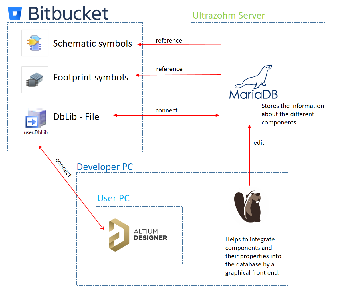
Fig. 124 Overview of the databased system for Altium.#
The library system splits up in three different locations:
The altium_libraries repository. All schematic symbols and PCB footprints of the individual components as well as the DbLib file that is required to connect to the database on the UltraZohm server is located in this repository
The UltraZohm server: All component parameters like Manufacturer Part Numbers etc. are managed by a MariaDB database on the server. In order to edit database records a separate database client (e.g. DBeaver) is recommended.
User’s PC: The PC of the PCB developer gets access to the locations 1 and 2 and the developer is able to place the components. In case he has write access he can also edit and add components.
In the following, the individual tools and necessary installation steps are discussed.
Note
All usernames and passwords can be obtained from the UltraZohm core developer team. Please get in touch via the Slack channel!
In order to use the database driven library for Altium, a few settings need to be made initially.
In the following chapters are a guideline on how to install and set the parameter is given.
The following tools are required:
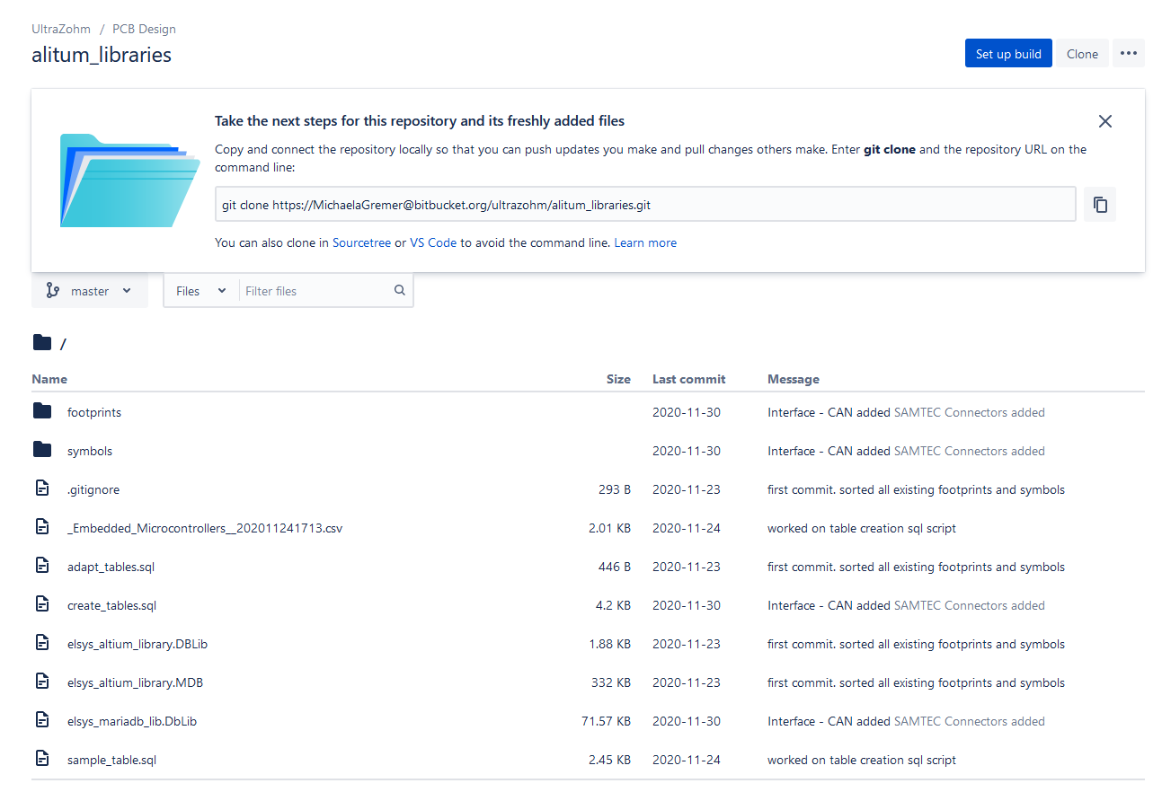
To work with the databased library system in Altium, it is necessary to get access to the Bitbucket system of the UltraZohm, especially to the altium_libraries repository
If you intent to add new components, create a new feature branch. Follow the naming convention feature/<meaningful_name>. If the git shell interface is used the command is gitcheckout-bfeature/<branch_name>
If a new component was added, commit and push the new component to Bitbucket
When component editing is finished open a pull request on Bitbucket. The components will be reviewed and merged into the master branch.
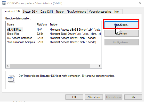
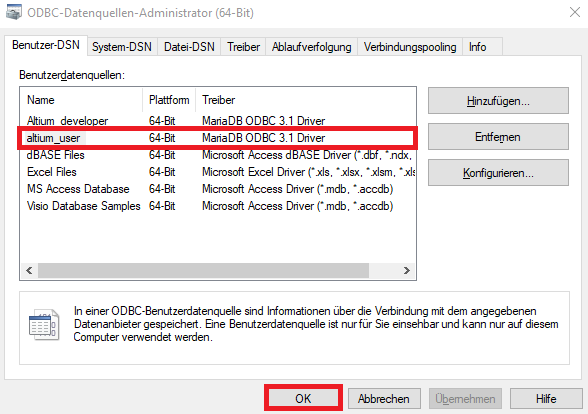
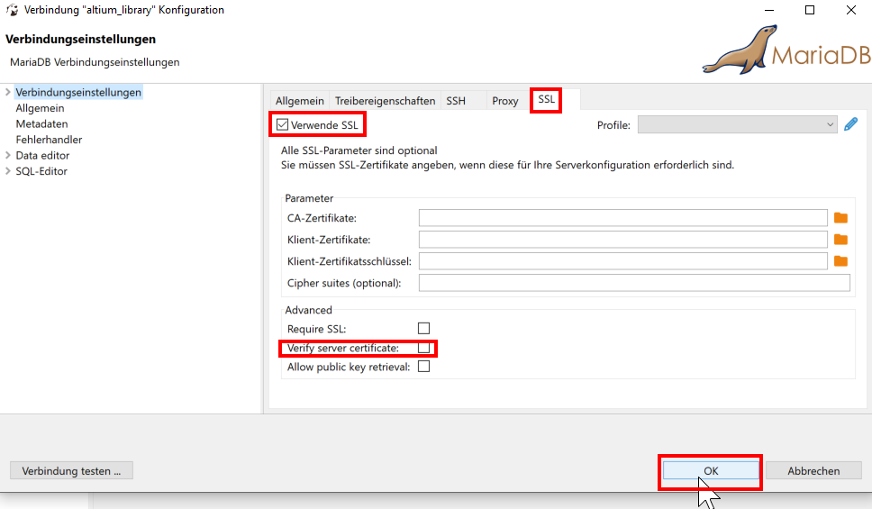
The ODBC connection is read only because no changes on the database will be made from Altium directly. A separate database client e.g. DBeaver is used to edit the database (see Integration in Altium).
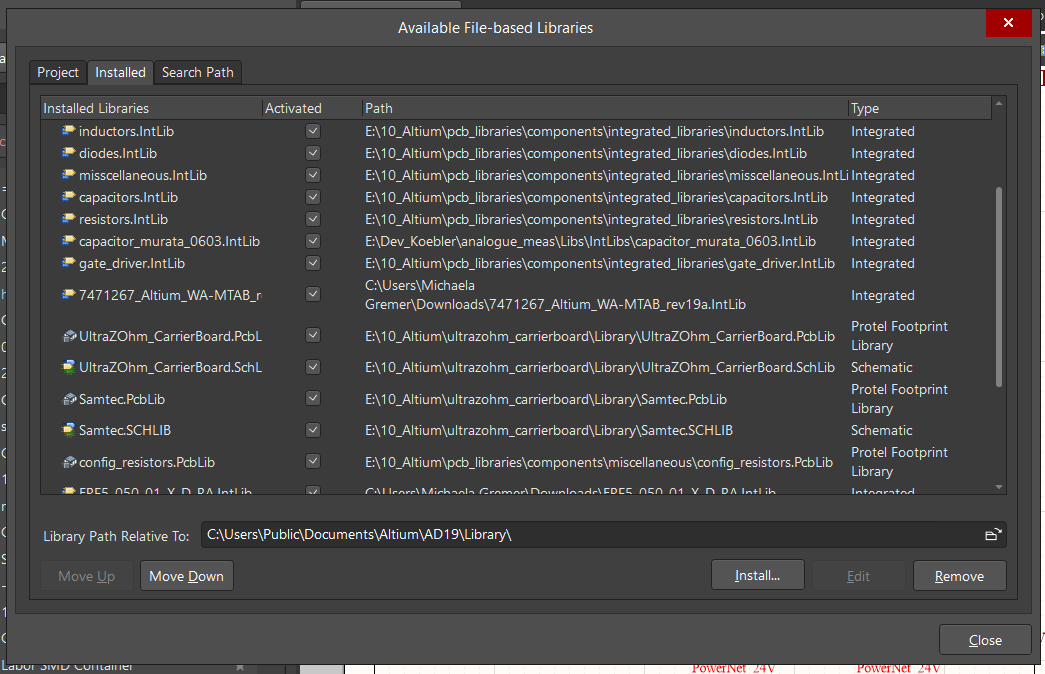
Click on the three horizontal lines and select the point File-basedlibraryPreferences
Select the register Installed. While not necessary, it is strongly recommended to remove all not required libraries at this point (e.g. the standard “Miscellaneous Devices” library from Altium)
If new components are required the developer will need write access to the Bitbucket repository and to the database on the UltraZohm server.
A dedicated user called altium_developer is available on the database system for this purpose. He has write access to the whole library database.
As a graphical database client DBeaver is recommended.
In the following chapter the procedure to add a new component is illustrated by adding an SMD capacitor. The following chapter only explains the addition
of the component to the repository and the database. Furthermore, the developer who adds the component has to make sure that the footprint followsthe mapping of the mechanical layers. See Mapping of the mechanical layers for further information. If the component does not follow this mapping the pull request will
not be accepted.
Note
The goal of this database system is that schematic and footprints of generic components only exist once.
This means that schematics and footprints symbols of generic components only have to be in the Bitbucket repository once, even if there are multiple physical components available (e.g. different manufacturers and values).
Only if the component has a different geometry or pinout, a new schematic and/or footprint must be added.
The number of pins on the symbol must match the number of pins on the footprints. The mapping of the pins is done with the pin numbering (pin 1 of the symbol is mapped to pin 1 of the footprint and so on).
In case of doubt the symbol and the footprint supplied by the manufacturer must be used instead of using an existing footprint.
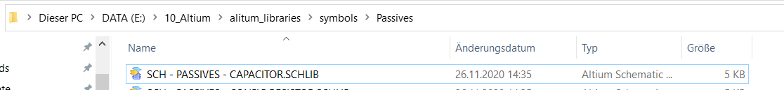
Check if the schematic symbol already exists as a symbol in the Bitbucket system. The schematic symbols are located under alitum_libraries\symbols If the schematic does not exist, copy the schematic symbol in the suitable directory under alitum_libraries\symbols. It is vital that the .SchLib file only contains one symbol. See Symbols and Footprints on how to extract the symbol from different sources.
Follow the naming convention for the .SchLib file SCH - <directory> - <description>.SCHLIB
Note
The extension of the file is written in capital letters.
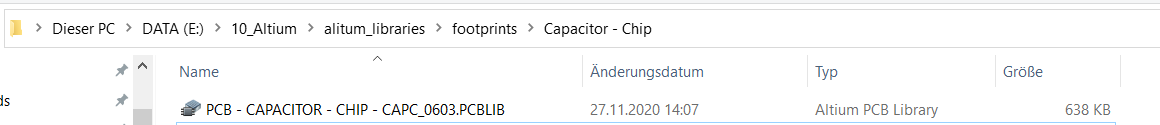
Check if the footprint symbol already exists in the Bitbucket system. Use the IPC-7351B naming convention when searching for the footprint. If the component does not exist copy the footprint in the suitable folder of the footprints \alitum_libraries\footprints. It is vital that the .PcbLib file only contains one footprint. See Symbols and Footprints on how to extract the symbol from different sources.
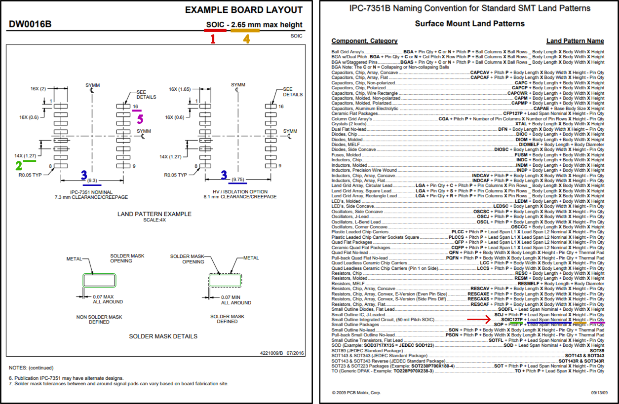
Follow the naming convention for the .PcbLib file PCB - <directory> - <description>.PCBLIB. Try to use the IPC-7351B naming convention for <description> and make sure to use the same name for the footprint name property which is used as FootprintRef in the MariaDB.
Fig. 148 IPC-7351B name generation example for SOIC127P930X265-16.#
Note
The extension of the file is written in capital letters.
Switch to the DBeaver tool
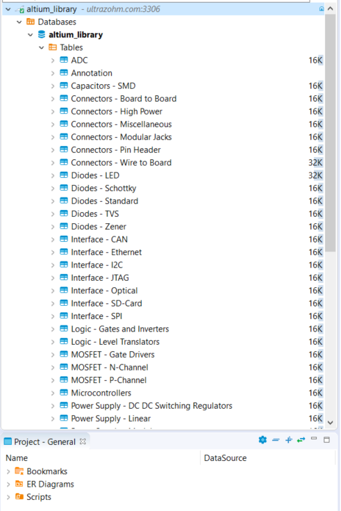
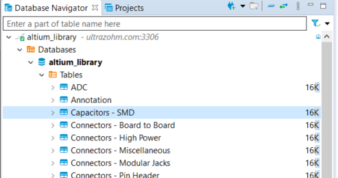
Choose a suitable table where the component should be added. If no table is suitable go on with the instruction given in section Addition of a new table.
Warning
This option must only be chosen after talking to your supervisor and must be announced in a pull request.
When adding a new table, the .DbLib file, which implements the connection from Altium to the database, must be changed and all users need to update the file in order to get access to the new table.
In case of doubt put the component in an existing table. The current amount of tables should be sufficient to fulfill the requirements.
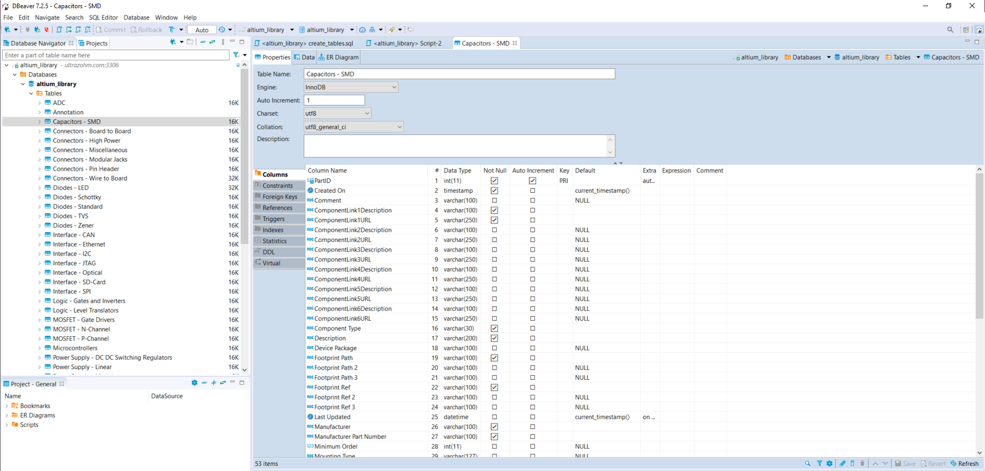
A new register on the right side with the table will appear
Fig. 150 DBeaver - Editor will open on the right side.#
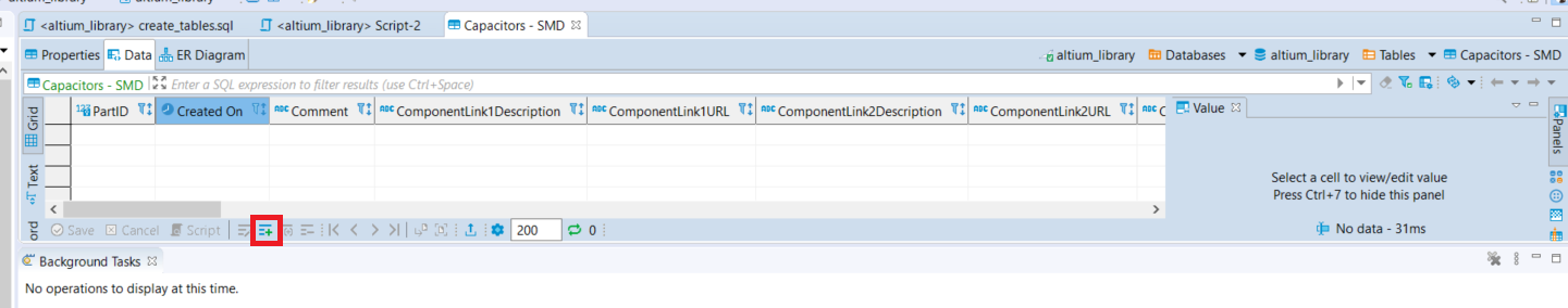
Switch to the “Data” register. An overview of all already added components will be shown there.
Fig. 151 DBeaver - change to tab “data”. In this case, no component is still existing in the table.#
Press the add button and a new row highlighted in green appears.
Double click on a cell to enter content.
To switch between the view of all components and the comfortable editing mode for one component –> presstab.
12. If all necessary cells are filled with information, save the components with the save button (under the current table on the left side or by pressing Ctrl+S).
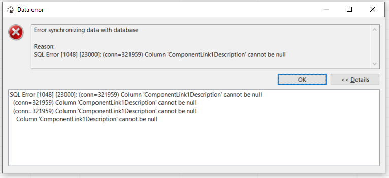
Some cells are constraint to be NOTNULL. These cells must be filled before saving is allowed. If those cells are not filled the following message will occur.
Press OK and fill out the missing cell (in this example, “ComponentLink1Description”).
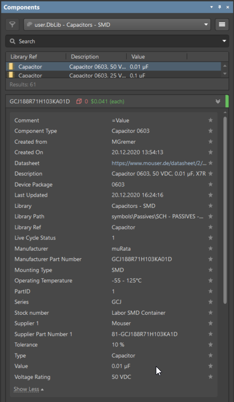
The table cells, which are here described in detail is from “Capacitors - SMD” table as an example.
LCSC Part Number component description for ordering and assembly at JLC PCB
Stock number
Labor SMD Container
Stock number of the ELSYS component stock
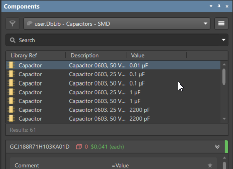
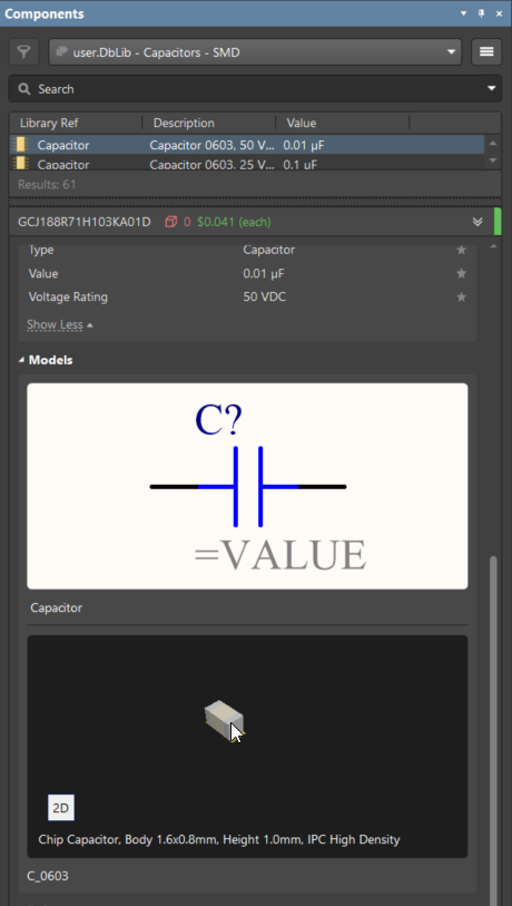
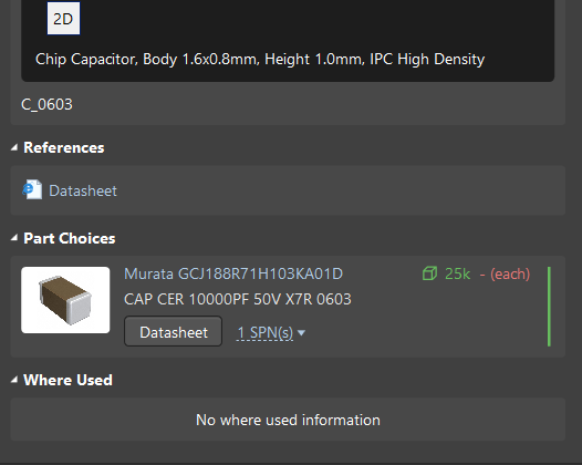
If the component is saved in DBeaver, refresh the view in Altium via F5 –> choose place –> part and select the library where the component has been added –> the new component is shown with all the inserted database information
At the end of the adding process of a component commit and to push the new components for other users in Bitbucket and open a pull request to the master branch.
This option must only be chosen after talking to your supervisor and must be announced in a pull request.
When adding a new table, the .DbLib file, which implements the connection from Altium to the database, must be changed and all users need to update the file in order to get access to the new table.
In case of doubt put the component in an existing table. The current amount of tables should be sufficient to fulfill the requirements.
If the component you intend to add does not fit in the existing tables a new table must be created. In the following this procedure is described:
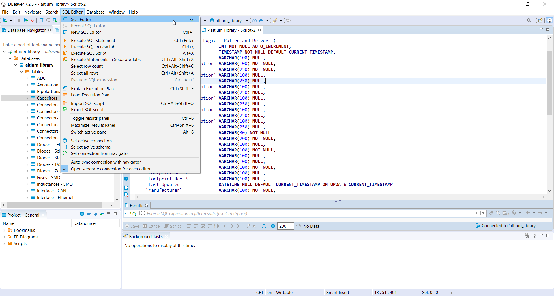
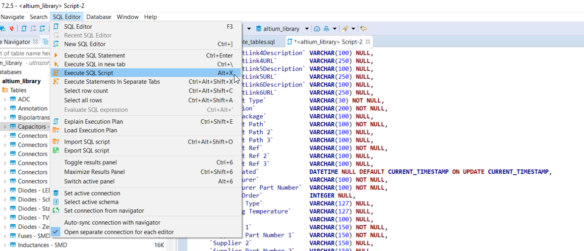
Open the SQL Editor in DBeaver
Fig. 157 DBeaver - Open the SQL Editor in DBeaver.#
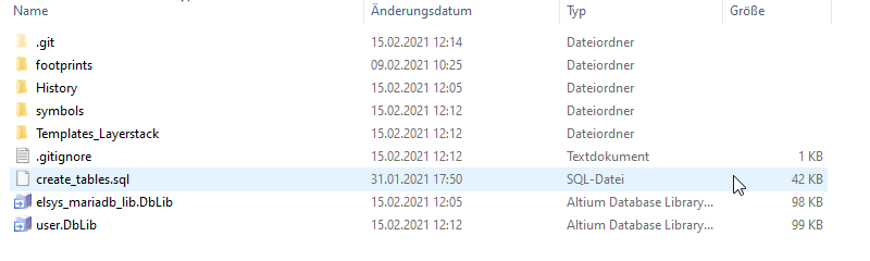
On the Bitbucket system the sql File “create_tables.sql” is available
Fig. 158 Bitbucket folder - Open the sql File “create_tables.sql”.#
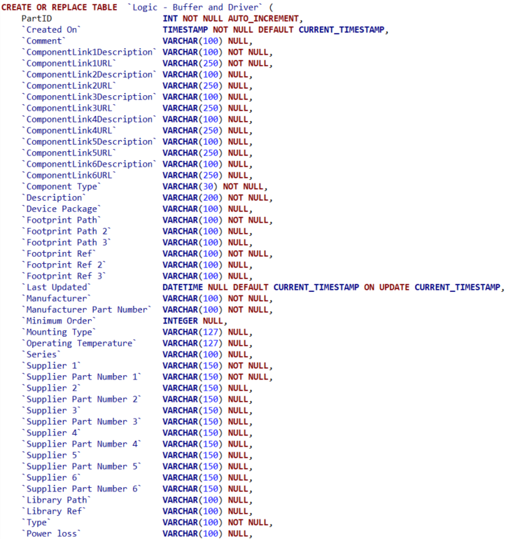
In this file you can find the syntax for creating a new table.
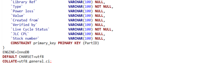
Create the various relevant table columns by copying the following rows:
Now it is possible to add new components to this table by following the instructions in section Addition of a new component.
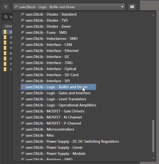
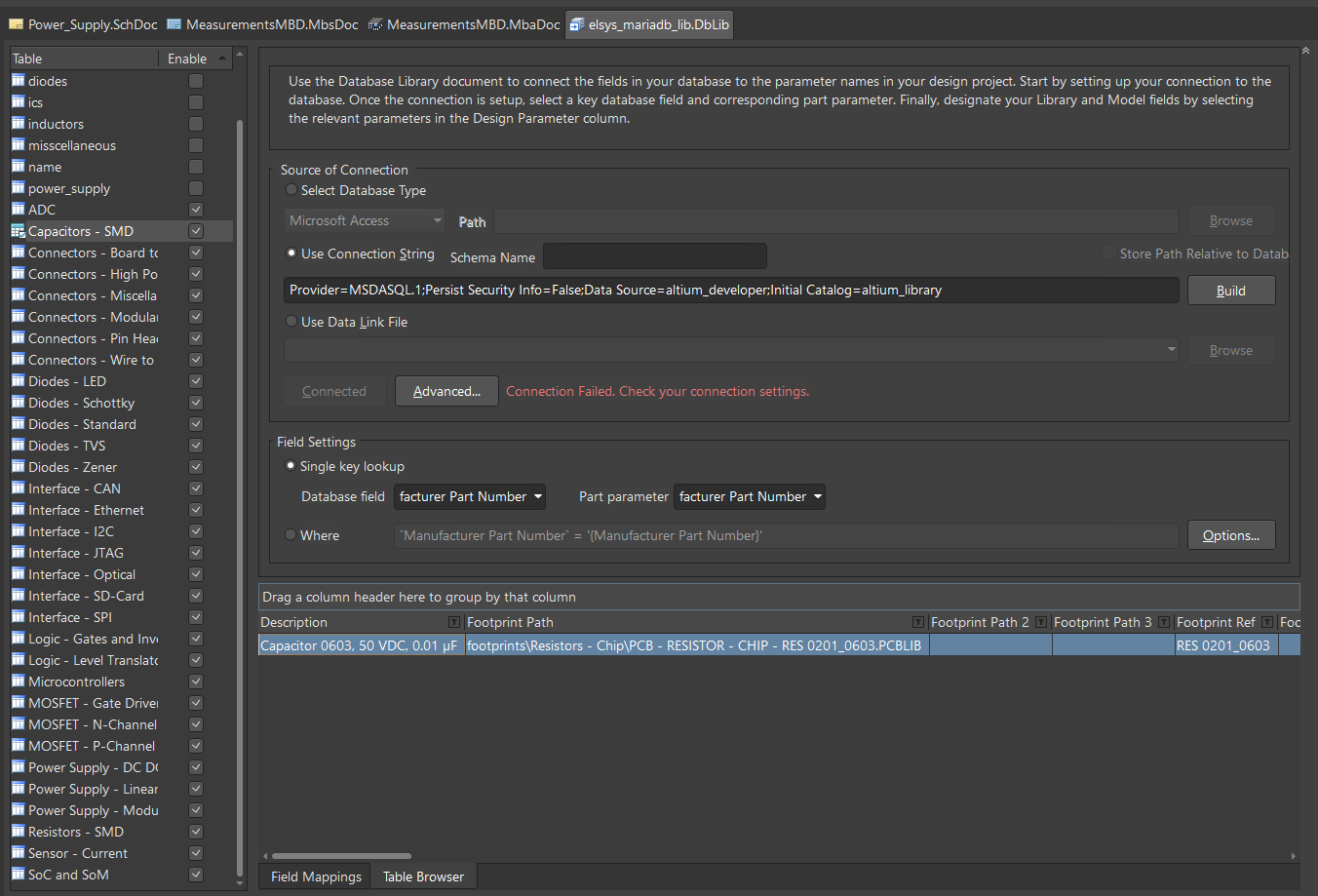
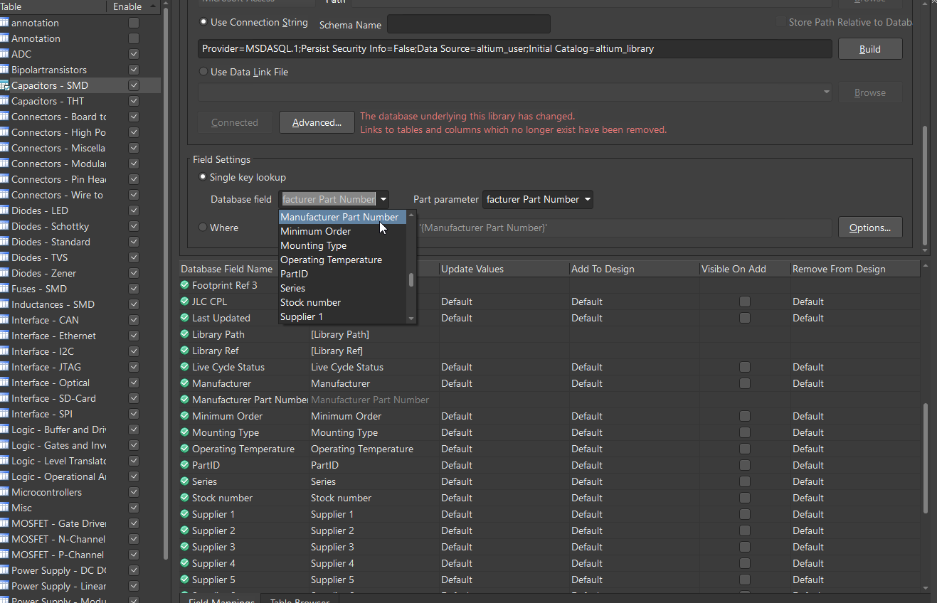
7. If components were added to the table, it is necessary to change one setting in Altium for this table once.
Therefore, open the “user.DbLib” file in Altium.
Select the necessary table.
Change under Field Settings the point Database field from “choose field” to Manufacturer Part Number