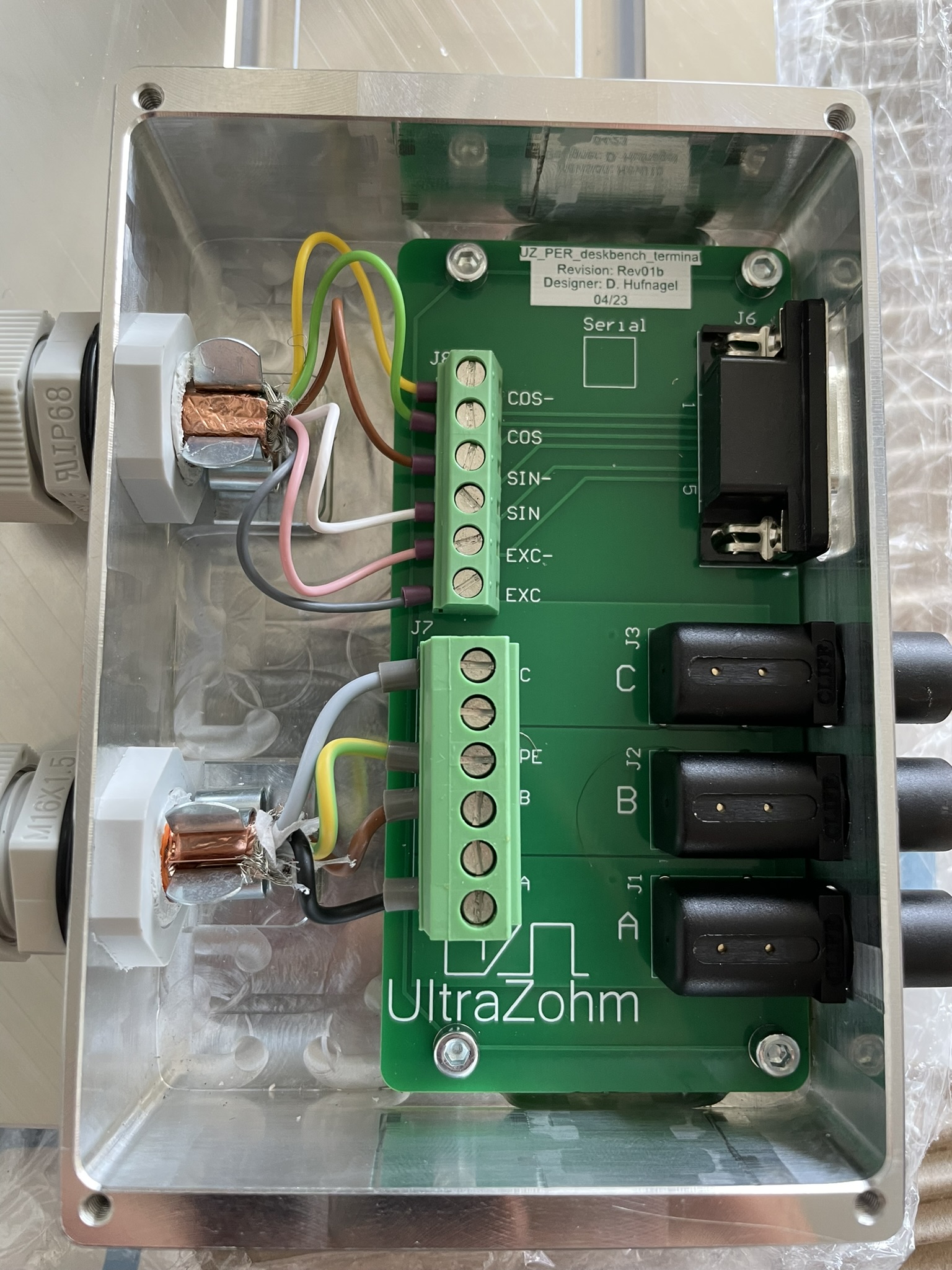
uz_per_deskbench_terminal PCB#

Fig. 274 uz_per_deskbench_terminal PCB#
Source#
General description#
This PCB is designed to connect a 3-phase PMSM with a resolver to the Deskbench. The PCB is housed in an enclosure and serves as an interface between the Deskbench and an inverter, typically the Digital Inverter Rev03.
Variants#
The PCB comes in two variants: one with an optional motor brake connection and another one without it. Currently, only the variant without the brake connection is used.
Fig. 275 Functional areas of the uz per deskbench terminal PCB#
Layout#
The PCB is structured by functional areas as shown in Functional areas of the uz per deskbench terminal PCB above.
Terminal Connector for resolver
Terminal Connector for motor
Output DSUB to UZ with Digital Resolver Rev01
Lab socket to inverter Digital Inverter Rev03
Color |
Pin Terminal |
PIN DSUB 9 |
|---|---|---|
Yellow |
COS- |
4 |
Green |
COS |
3 |
Brown |
SIN- |
2 |
White |
SIN |
1 |
Pink |
EXC- |
6 |
Grey |
EXC |
5 |
Color |
Pin Terminal |
PIN Inverter |
|---|---|---|
Black |
A |
Phase A |
Brown |
B |
Phase B |
Grey |
C |
Phase C |
Green-yellow |
PE |
NC |
Red |
Brake+ |
NC |
Black |
Brake- |
NC |
Downloads#
Designer#
Designed by Dennis Hufnagel(TH Nürnberg), 04/2023