Wolfspeed Inverter 2L 25kW Interface#
Source#
General Description#
This PCB is designed to interface the UltraZohm with the Wolfspeed CRD25DA12N-FMC 25 kW Three-Phase Inverter. It plugs directly into the Wolfspeed inverter in place of the Texas Instruments TMDSCNCD280039C control card.
Analog measurement signals are routed via an RJ45 connector to the UltraZohm ADC board using fully differential signaling. Digital control and status signals are transmitted over optical links using HFBR transmitters/receivers.
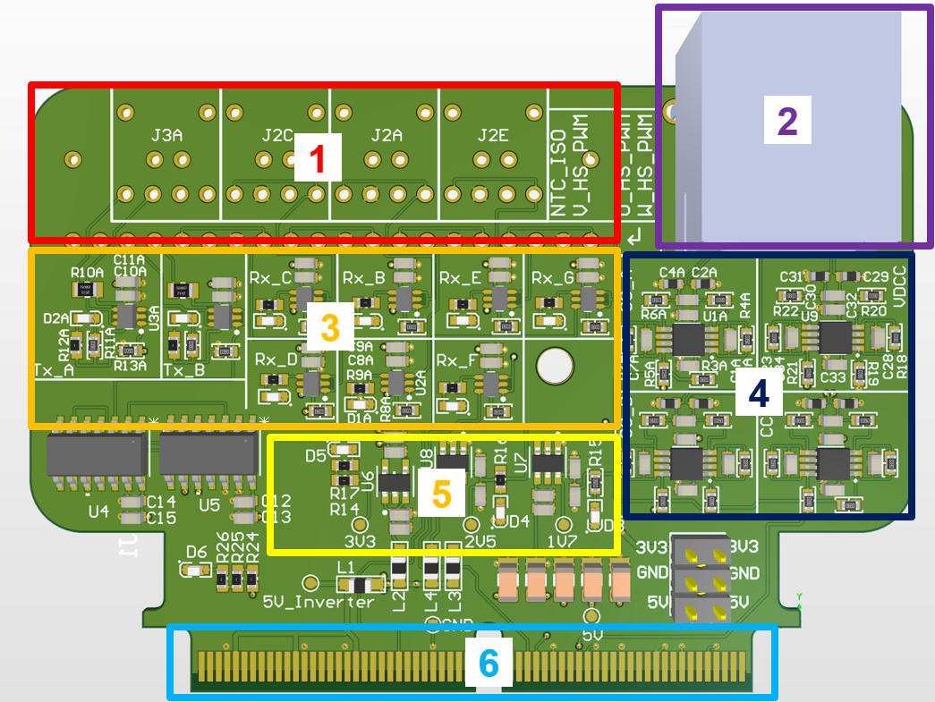
Fig. 305 Functional areas of the uz_per_wolfspeed inverter interface pcb#
Layout#
The PCB is structured by functional areas as shown in Functional areas of the uz_per_wolfspeed inverter interface pcb.
HFBR-1521Z/2521Z Digital optical transmitters and receivers
RJ45 port for analog signal transmission
Driver stages for the optical links
TI THS4561 fully differential amplifier stages for differential signaling
Power section: TPS7A20 (3.3V LDO), REF35 (2.5V and 1.7V references)
Samtec HSEC8 120-pin edge-card connector mating with the Wolfspeed inverter
Signal Description#
The interface board adapts all required signals between the Wolfspeed inverter and UltraZohm. Signals are grouped as analog and digital.
Analog Signals#
The signals on the inverter side are single-ended and converted to fully differential signals for noise-robust transmission to the UltraZohm ADC board. The adapter cards scales the single-ended signals by factor 1.5038 (10/6.65) to match the analog range of the Wolfspeed inverter (3.3V) to the 5V analog input range of the UltraZohm ADC board. The reported total sensing gain is measured experimentally, see attached thesis for details. It includes the gain of the measurement device (e.g. current sensor) and the gain of the interface board. The bandwidth is determined theoretically based on an LTSpice simulation and the resulting -3dB point.
Signal |
Source |
Total Measurement Gain |
UltraZohm ADC Channel |
|---|---|---|---|
Phase Currents U, V, W |
LEM LAH 50-P |
total sensing gain 0.02417 in V/A, bandwidth ~50kHz |
I_U (Ch1), I_V (Ch2), I_W (Ch3) |
DC-Link Voltage |
voltage divider, non-isolated |
total sensing gain in 0.003744 Vsec/Vprim, bandwidth ~7kHz |
V_DC on Ch4 (RJ45 Pair 1-2) |
Digital Signals#
The overcurrent detection signal is active LOW, meaning that when an overcurrent condition is detected, the signal goes LOW and, therefore, the LED of the transmitter is OFF. The overcurrent limits are by default set to +-79A and can be adjusted by varying the reference resistors, as detailed in the Wolfspeed documentation.
The NTC output is converted to a 50 kHz PWM signal with varying duty cycle.
Signal |
Direction |
Conditioning |
Notes |
|---|---|---|---|
6x PWM Gate Signals |
UZ → Inverter |
Optical Rx |
High- and Low-Side for 3 phases, dead-time generated in UZ |
Gate Driver Disable |
UZ → Inverter |
Optical Rx |
Global gate driver shutdown |
6x Overcurrent Detection |
Inverter → UZ |
AND-gates (SN74HCS08DR) + Optical Tx |
Consolidated into single fault signal (active-LOW) |
NTC Temperature |
Inverter → UZ |
Optical Tx |
PWM modulated signal at 50kHz |
Testing#
Tests were performed up to 10kW using an RL-load with a 14Ohm resistor and 1mH inductor
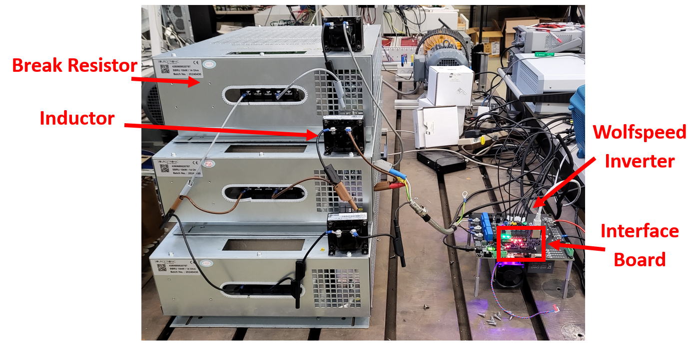
Fig. 306 Integrated testing setup with RL-load#
Stable three-phase sinusoidal currents measured using a Rohde & Schwarz MXO 5 series oscilloscope (2GHz, 8 channels)
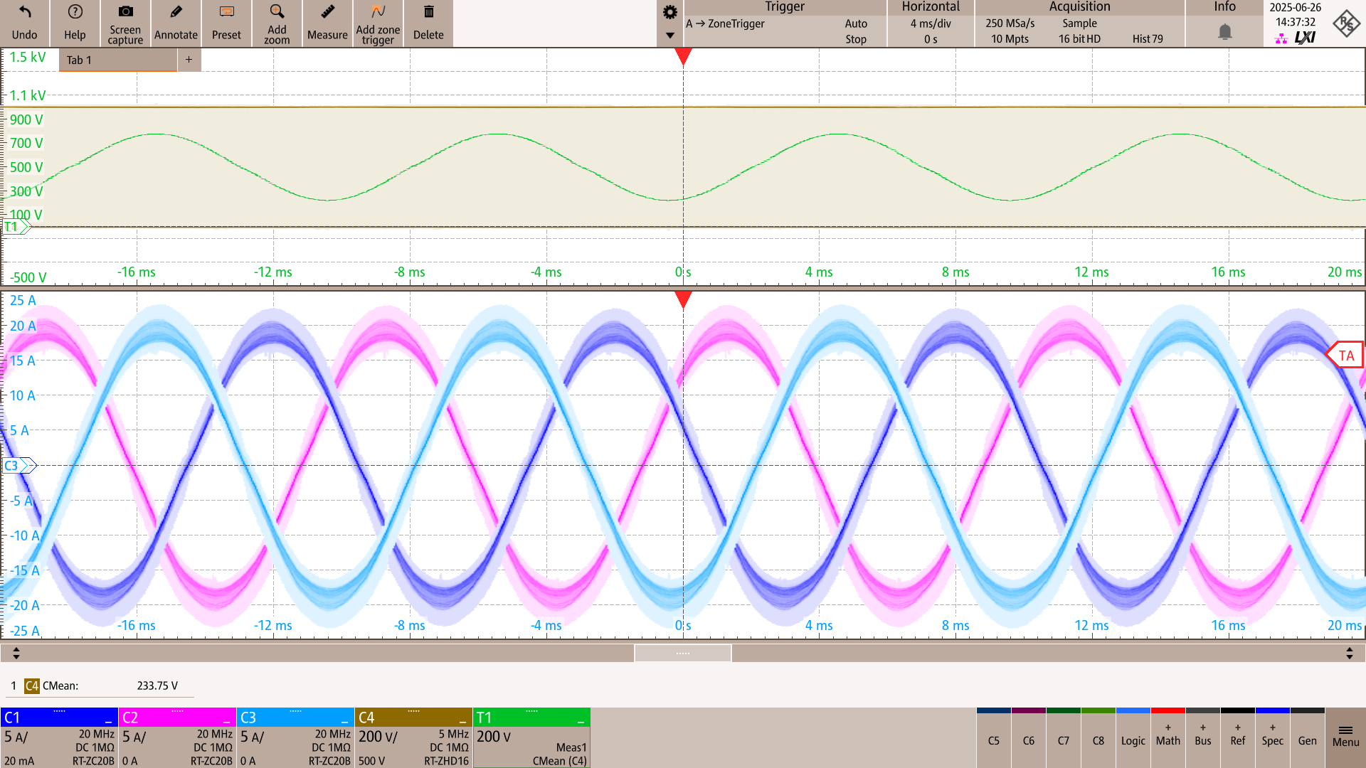
Fig. 307 Oscilloscope measurements of the output phase voltage at a 100kHz switching frequency with a 999V/8.33A DC-link input#
Notes for Future Revisions#
A few considerations should be kept in mind for future iterations of the interface board:
Edge connector pinning: The HSEC8 120-pin edge card connector from Samtec uses a different numbering scheme than the TI control card. Care must be taken when mapping pins to avoid interface mismatches. Details in TI E2E Forum
Mechanical stability: A 3D-printed support stand was added in the current design to keep the board mechanically sturdy when plugged into the inverter. The step file of the stand can be found on the Bitbucket repository.

Fig. 308 Interface board with 3D-printed stand for mechanical stability#
Software Branch We used the
feature/wolfspeed_inverter_adapterboardbranch of the ultrazohm_sw repository to test the inverter. View the branch diff directly here.
Documents and Links#
Bachelor thesis
download hereFinal presentation
download hereSchematic Rev03
download herePoster KI-Power Symposium
download hereAltium Files git Repo uz_per_wolfspeed_25kw_FM3
Wolfspeed 25 kW Three-Phase Inverter CRD25DA12N-FMC.
TI E2E Thread on HSEC8 pinout