Frontpanel Mainboard (Rev01)#
Fully PCB-based frontpanels are used exclusively in combination with carrier boards ≥ Rev05 (and are not compatible with earlier revisions/versions at all).
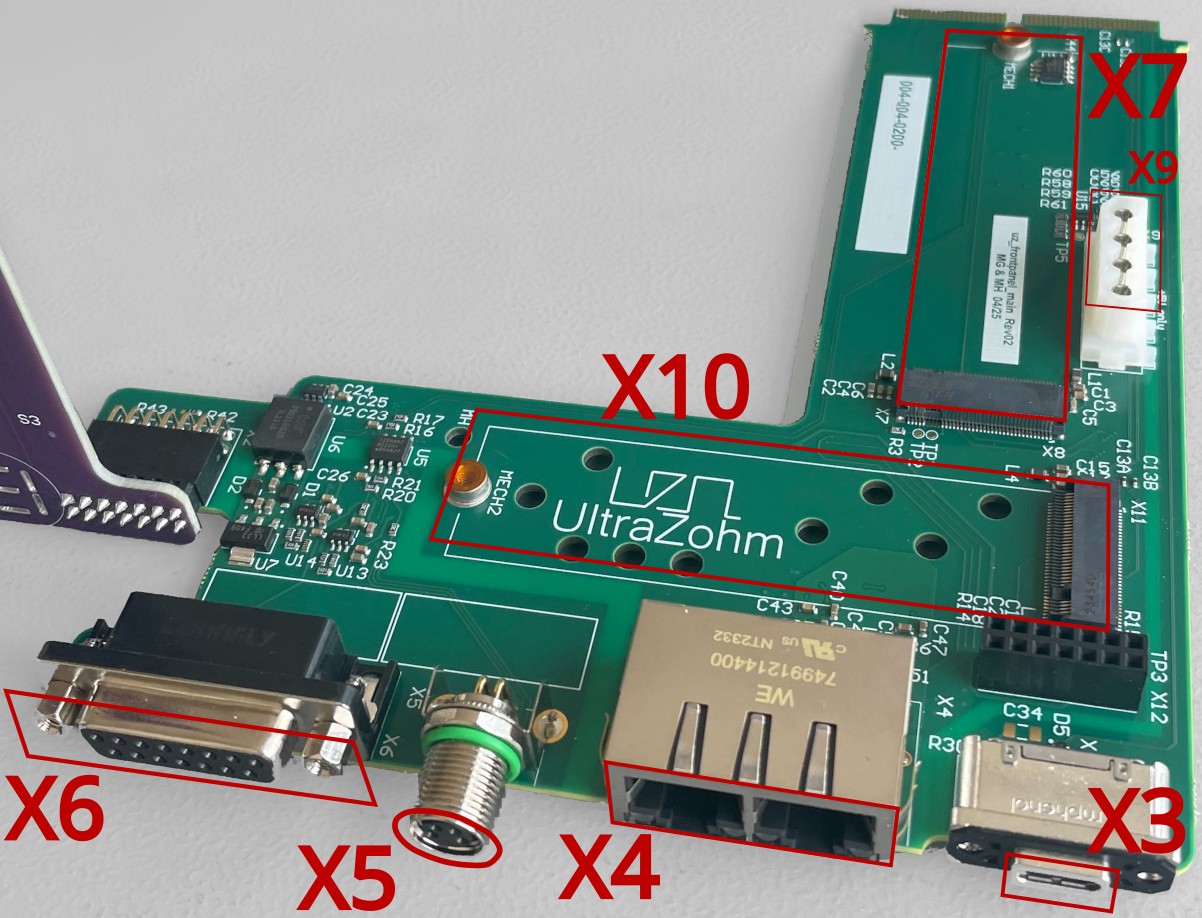
The frontpanel (FP) PCB contains the following connectors and features (cf. Summary of new Features and Changes of the new carrier for a higher-level summary):
X1is an internal PCB-based edge connector that links the FP to the carrier (connectorX1, cf. Frontpanel.SchDoc for details) whilstX2(_buttonboard) andX12(_firstfloor) link to the other frontpanel PCBs within the systemX3is a USB-C connector that accesses the integrated, isolated USB to dual-JTAG/UART interface on the carrier board. Please refer to the Step-by-step for IsoJTAG uz_per_jtag guide for details on JTAG programming.X4is a dual-port Ethernet connector that exposes the on-carrier (on the left, RGMII-based) and on-FP (right-hand side, via SGMII) PHYs to the outsideX5is the External STOP connector known from previous carrier boards (cf. External Stop for details). Note that pins 1 and 2 no longer are NC – Instead, they can be configured as additional I²C I/Os (cf.Extra01-2) by means ofU8.X6is a 15-pin D-Sub connector that provides up to 12 software- and/or up to five hardware-controlled I/Os. The former rely on a flexible I²C GPIO (cf.U8) that also interfaces the System Supply & Safety Component (S3C) (via an interrupt and a reset signal). The latter are fixed-direction (3x O, 2x I) signals (FlexIOs) that directly interface the S³C for time- and/or safety-critical functionalities like, e.g., heartbeats (NB: as the precise requirements are highly application-specific, no default implementation is provided as byuz_swet al.). Also note that the on-board supply is limited to 100mA for the entire isoIO circuitry, which limits the current that may be drawn externally.X7is an internal, 2280-sized M.2 slot that can be used to connect many off-the-shelf PCIe x1 extension cards. Due to limitations in the currentuz_sw, this feature requires manual PS configuration via Vivado’s PCW on the software side, whilst the PCIe reference clock on the FP has to be enabled by means ofR2. A 5V supply is available onX9(NB: observe connector/cable pin-out and maximum supply current) if required by the M.2 PCIe card.X10is an internal, 2280-sized M.2 slot for a 6-Gbit/s-SATA3 SSD (which is supplied from the carrier’s3V3_PERrail and, thus, subject to its limits)
For pin-outs and more details (in particular w.r.t. the isoIOs), please refer to the schematic of Frontpanel Mainboard (Rev02) as the pin-compatible successor.
Downloads#
Please refer to the uz_frontpanel_main repository for design files, the MPNs of the components used etc.