Sampling rate to get all 24 channels sampled of up to 125 kSPS (three MAX11331 chips work in parallel, while each of them sequentially samples 8 channels via multiplexer)
Resolution of 12 bit
Input range is 0..+5V with respect to ground of UltraZohm chassis for In_P and In_N, i.e., the maximum delta measuring range is 5V
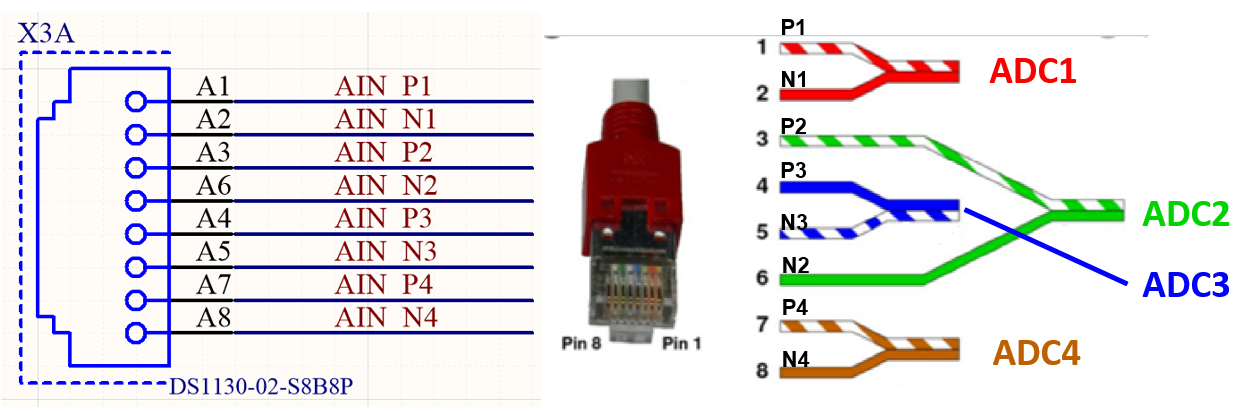
The pinout of the RJ45 ethernet plug is NOT intuitive, as shown in Fig. 243. Moreover, the pinout is flipped compared to the LTC2311 analog card, see Pinout of Analog Connector.
Note
Note that Fig. 243 shows an ethernet cable according to T568B!
Warning
It is essential to use Ethernet cables with shielding and metallic RJ45 plugs (e.g. CAT7 cables) so that the GND of the MAX11 card (connected from the PCB GND to the RJ45 connector housing) and the GND of the measuring signal source are connected. Without this GND connection, there will be floating signals, i.e. common mode interference on the measurement signal.
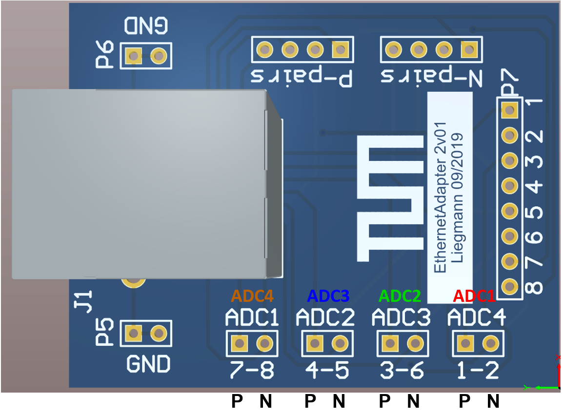
We provide a breakout board for the RJ45 cable that matches the ADC card. P is the positive analog input, N the negative.
Note
Note that due to the flipped connection (compared to the LTC2311 assignment) the colored nomenclature applies for MAX11331 adapter board.
The pairs of the RJ45 ethernet connector map to the ADCs as follows:
Connected
Pin on RJ45
ADC
\(V_\mathrm{in,p}\)
\(V_\mathrm{in,n}\)
ADC 1
1
2
ADC 2
3
6
ADC 3
4
5
ADC 4
7
8
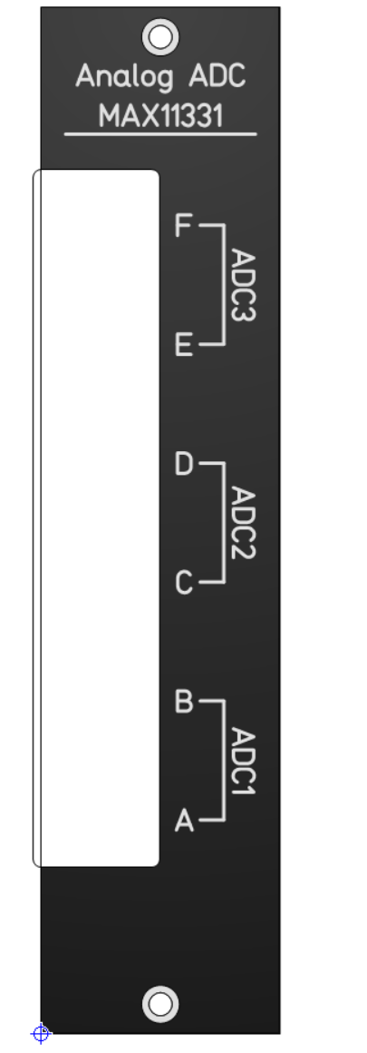
The MAX11331 adapter card has six of the RJ45 ports described above (Port A…F), whereby two consecutive RJ45 ports are evaluated by one of the three MAX11331 ADC chips. The driver of the IP Core ADC ADC MAX11331 V1 shows exactly this nomenclature, i.e., ADC_A1…ADC_F24.
Fig. 244 Frontpanel of the MAX11331 adapter card on the UltraZohm.#
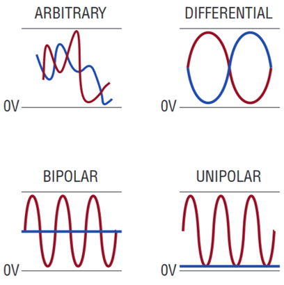
There are three ways to measure an analog signal with this adapter card
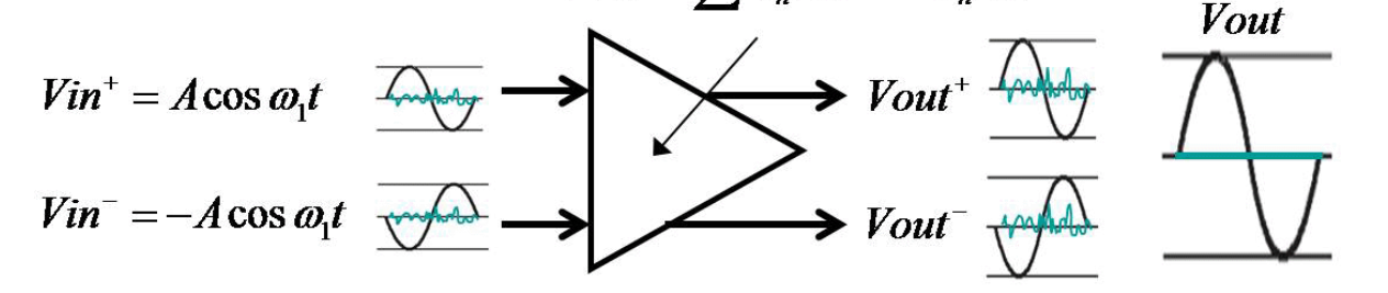
Fully differential (bipolar)
Single-ended with reference to an offset voltage (bipolar)
Single-ended with reference to ground potential (unipolar)
Fig. 245 Different input voltage forms for measurement.#
Warning
In all cases, the input range for each analog pin (In_P, In_N) is 0..+5V with respect to UltraZohm ground.
It is forbidden to apply voltages above 5V or below 0V on the connector.
The IP Core ADC ADC MAX11331 V1 interacts hereby with the MAX11331 IC and can change the input range of each differential pair by setting the UNIPOLAR, BIPOLAR, and RANGE registers.
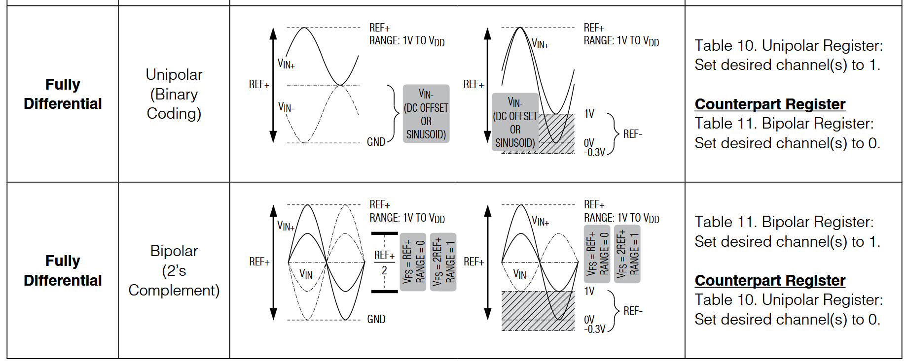
Fig. 246 Analog input configurations and waveforms, see Table 8 in [MAX11331_datasheet]#
Note
In all cases, both input voltages (In_P, In_N) should be transferred over the same twisted-pair cable to get the same common-mode noise on both lines, which is then rejected by the differential amplifier.
This will yield the highest signal-to-noise ratio (SNR) even when using longer cables.
The IP Core ADC interacts hereby with the hardware in the BIPOLARregister=1 and RANGEregister=1 which defines the input range to be ±5V. In this case, all 12 Bits resolution of the ADC are utilized.
This is the recommended use-case and the default case setup of the IP core.
2. Single-ended with reference to an offset voltage (bipolar) measurement#
The negative input In_N is set to a fixed offset voltage, e.g. 2.5V which is often provided by the current sensor. The positive input may vary between 0V to 5V.
In the default case setup of the IP core, i.e., RANGEregister=1, only 11 Bits resolution of the ADC are utilized.
The full 12 Bits could be used by setting RANGEregister=0 which changes the input range to ±Vref/2, i.e., -2.5V to +2.5V (tbc).
3. Single-ended with reference to ground potential (unipolar) measurement#
The negative input In_N is set to ground which is preferably transferred over the same cable as the measurement signal In_P.
In the default case setup of the IP core, i.e., BIPOLARregister=1, only 11 Bits resolution of the ADC are utilized.
Note that the bit pattern has to be interpreted differently, see Figure 4 and 5 in [MAX11331_datasheet] .
The full 12 Bits could (probably) used by setting UNIPOLARregister=0 which sets the input range to 0..5V (tbc).