I²C/SSD/S²C Extension Board retrofit (≤ Rev04)#
Revisions#
There are three major, feature-distinct revisions of this board:
Rev01 (from 2022) only includes I²C components for basic Linux support, i.e., a general-purpose EEPROM, GPIO, an RTC and MAC EEPROMs
Rev02 (from 2023) adds two M.2 slots for SATA SSDs and hooks into the carrier/frontpanel link for access to LEDs, buttons and supply
Rev03 (from 2025) adds a variety of features to (partially…) align existing Rev04-based systems to the features of ≥Rev05 carriers
Features of Rev03#
Overview#
General-purpose and MAC EEPROMs, RTC, M.2 slots for SATA SSDs and frontpanel link-up as the two previous revisions of the board (cf. above)
Integration of an S³C-like management component (“S²C”) that
interfaces with
the previously-unused twelve “DIG_IO” signals of adapter card slot D5,
the “system I²C” (PS_I2C1) bus to integrate, e.g., the frontpanel GPIO functionalities,
SPI0 (which, alternatively, can be forwarded to outside devices, e.g., by means of the twelve signals on D5),
the 11+1 “isoIOs” (i.e., PS-MIOs) out of which six are carrier outputs, five are carrier inputs and one is the External STOP, and
two on-board (and thus not-easily-reached) push buttons;
monitors the VIN supply (and, e.g., MIO-based SoM watchdogs) to inform the outside world of the system’s status; and
provides additional I/Os (connectors
X1andXc1plus TPs) for user extensions (voltage rails 1V8 and/or 3V3)
Integrated thermal management for
configuration-free temperature-driven control of up to two fans, and
monitoring of fan status, internal temperature and an optional diode
Integration of the USB-to-JTAG/UART boards (i.e., 2x TE0790 or the custom, optional single-board solution of some UZs) with the following advantages
Isolated JTAG+UART interface to avoid ground loops during debugging
Dual-JTAG to program both SoM and D-slot CPLDs using a single cable
Dual-UART (from SoM to USB) for independent consoles of RPU and APU
Note that the second JTAG channel (connected to S²C and slot CPLDs) follows a different “switching strategy” than ≥Rev05 carriers – see below for details
Isolation of all but one of the links between carrier and extension board (per isolation domain on the extension board) to avoid ground loops
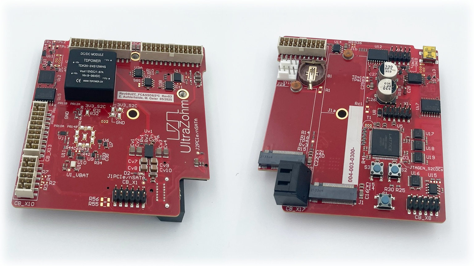
Block diagram#
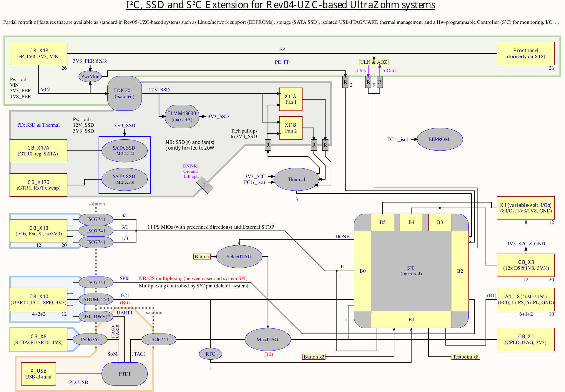
See the last page of the schematic for a higher-quality version of the above figure. Colored boxes mark separate isolation domains. Note the (power and current) limits of the supply rails, in particular when using two M.2 SSDs.
The CB_ connectors (left-hand edge of the diagram) link the extension board to the carrier.
Note that CB_X3 also has to be connected at all times, even if the 12 D5 signals are unused.
The CB_X1 link replaces the (sometimes fitted) second USB/JTAG module for CPLD programming.
Usage hints#
Both the integrated JTAG+UART interface and the not-really-on-carrier “UZP EEPROM” are programmed with the (four-digit) serial number of the overall UltraZohm system as a part of their identifier. This has a number of helpful “side effects”, which makes it easier to work with the single (or even multiple) system(s):
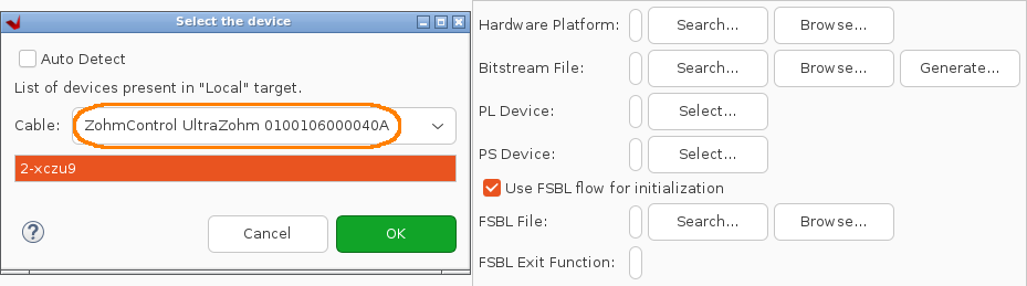
First of all, the stored serial number is visible in both Vivado and Vitis, and can be used to identify and address one particular system without manual selection of cables, JTAG targets, etc. during usage. In various dialogs, the serial number (e.g.,
0040) can be found at the end of the highlighted strings in the figures below (with Vivado on the left and Vitis – after clicking “Select” – on the right).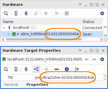
Secondly, users that rely on Linux on their host PC benefit from “nicely named” UARTs (i.e., the “COM ports” in Windows) thanks to sensible udev rules (in, e.g., Debian and Ubuntu). Automatically generated links in
/dev/serial/by-id/point to the four/three channels of the FTDI chip used. Like in Windows, the two lastttyUSBs created (i.e.,2and3when no other UARTs are connected, thus starting at0) are the two UARTs of the Zynq PS, with the first of the two being the one used by the UltraZohm software:/dev/serial/by-id/usb-Xilinx_UltraZohm_0100106000040-if02-port0 -> ../../ttyUSB2 # uz_sw /dev/serial/by-id/usb-Xilinx_UltraZohm_0100106000040-if03-port0 -> ../../ttyUSB3 # Linux
These names stay the same even if the system is dis- and reconnected or the PC is rebooted.
Technical notes#
As SPI0 (from the carrier board) only has a single CS pin, the two “sub-SPIs” of the S²C can only be used alternately (which is controlled by the
SPI0_SelS̅Y̅S̅USRnCSsignal on bank 2)SPI0 can also be forwarded “through” the S²C; to do so, disable the S²C’s integrated SPI controller (which turns all SPI pins into regular fabric I/Os)
Currently, the extension board has been tested only with Rev04 carriers, although retrofitting earlier systems should also work with fewer features, e.g., no SSDs (due to lack of PS-GTR connectors on older carrier boards)
Second JTAG channel#
As long as the S²C is unprogrammed (i.e., no bitstream resides in its internal Flash), the second JTAG (i.e., “B”, cf. Step-by-step for IsoJTAG uz_per_jtag) channel exposes the S²C so that it can be programmed.
Once the S²C is programmed, the second JTAG switches to the five D slot CPLDs and remains there, making the S²C “invisible” and protecting any, e.g., safety-relevant functions on it.
To regain access to the S²C via JTAG (in contrast to SPI and I²C as other means of configuration), button S1 has to be pushed – which returns the second JTAG channel back to the S²C for a single reconfiguration cycle – or until the next power cycle – only.
LED D3 indicates whether the S²C (on) or the D slots CPLDs (off) is/are currently selected.
All three remaining paths (JTAG and both UARTs) are always routed to the SoM.
Additional I/Os#
There are three types of available I/Os:
Eight 1V8 or 3V3 (depending on the externally-supplied
VIOvoltage) I/Os of bank 5 onX1, which also provides 1V8, 3V3 and GNDEight 3V3 I/Os of bank 1 on TPs 5 to 12, whilst
TP13xprovide access to the system’s 3V3 supply andTP14xare connected on GNDA special-purpose 3V3 pin header (
Xc1) with RC filters targeting the S²C’s secondary I²C controller and seven general-purpose I/Os
Retrofitting steps#
Prerequisites#
One I²C/SSD/S²C extension board (Rev03)
Three plastic card guides (for chassis mounting)
Unless already installed: CR1220 battery for RTC
Optional: Up to two SATA cables (X17[AB]), up to two M.2 SSDs (1x 2242, 1x 2280) and up to two screws (M3)
Cables: 4x Samtec (some wrapped in polyester-braided sleeving for easy installation) plus 2x ribbon cables
X3: Long 20-pin Samtec cable (carrier ↔ extension)
X10: Short 12-pin Samtec cable (carrier ↔ extension)
X13: Short 20-pin Samtec cable (carrier ↔ extension)
The cable for X18 (frontpanel link) depends on the type of frontpanel installed
Option A (LEDs connected with individual wires): Long 26-pin Samtec cable (carrier ↔ extension)
Option B (LEDs connected by means of “Z board”): Short 26-pin Samtec cable (extension ↔ LEDs)
X8 (SoM JTAG) and X1 (CPLD JTAG): Short and long 12-pin ribbon cables with IDC-crimped connectors
For older systems with purely wire-based frontpanels, ensure that R36 is populated (0R 0603).
For newer systems where the LEDs are on PCB-based, “Z-shaped” frontpanels, R36 has to be DNP.
Further reading#
Please refer to the following references for more details.