Deskbench terminal PCB Rev01#
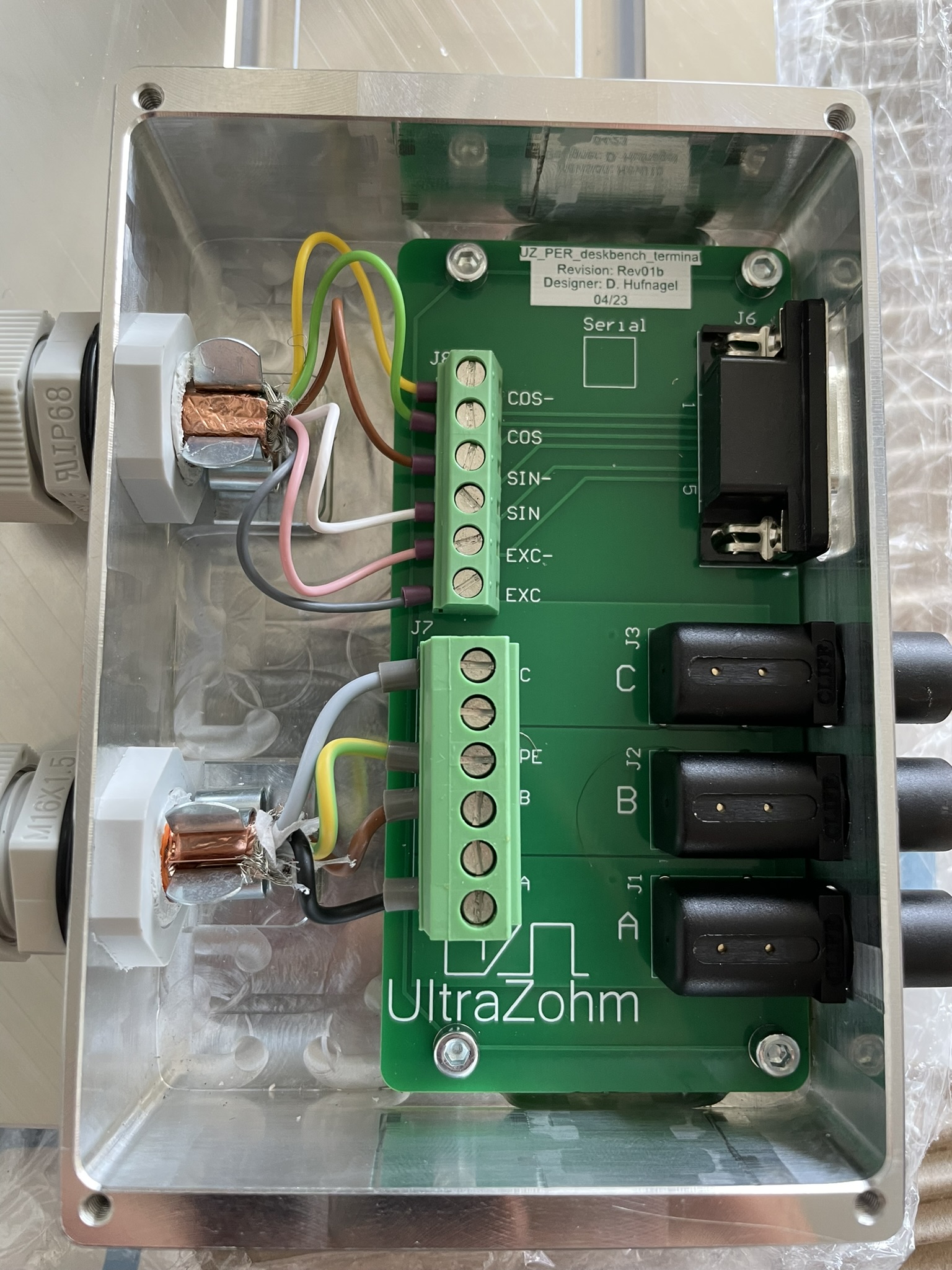
Fig. 318 uz_per_deskbench_terminal PCB Rev01 in housing#
Source#
General description#
This PCB is designed to connect a 3-phase PMSM with a resolver to the Deskbench. The PCB is housed in an enclosure and serves as an interface between the Deskbench and an inverter, typically the Digital Inverter Rev03.
Variants#
The PCB comes in two variants: one with an optional motor brake connection and another one without it. Currently, only the variant without the brake connection is used.

Fig. 319 Functional areas of the uz_per_deskbench_terminal PCB rev01#
Layout#
The PCB is structured by functional areas as shown in Functional areas of the uz_per_deskbench_terminal PCB rev01 above.
Terminal Connector for resolver
Terminal Connector for motor
Output DSUB to UZ with Digital Resolver Rev01
Lab socket to inverter Digital Inverter Rev03
Color |
Pin Terminal |
PIN DSUB 9 |
|---|---|---|
Yellow |
COS- |
4 |
Green |
COS |
3 |
Brown |
SIN- |
2 |
White |
SIN |
1 |
Pink |
EXC- |
6 |
Grey |
EXC |
5 |
Color |
Pin Terminal |
PIN Inverter |
|---|---|---|
Black |
A |
Phase A |
Brown |
B |
Phase B |
Grey |
C |
Phase C |
Green-yellow |
PE |
NC |
Red |
Brake+ |
NC |
Black |
Brake- |
NC |
Downloads#
Designer#
Designed by Dennis Hufnagel(TH Nürnberg), 04/2023