Performance Test Setup#
Overview#
This section describes the test setup used to validate the analog current measurement card for both DC and AC analysis. It includes equipment, configurations & calibration and the measurement methodology.
DC Analysis#
DC Test Purpose#
The DC analysis verifies the correct offset behavior and gain of the current measurement signal chain under static current conditions. It is used to confirm linearity, baseline voltage levels, and that the differential output behaves as expected when exposed to known DC input currents.
Equipment#
Keysight E36313A Triple-Channel Power Supply: Supplies 24 V DC for VIN input.
Keysight 34460A Digital Multimeter: Measures differential output voltage across the ethernet connector
AC Analysis#
AC Test Purpose#
AC test setup is used to evaluate the sensitivity and dynamic behavior of the current measurement box. The setup includes analog signal injection, probe configuration, and detailed usage of all test equipment.
Equipment#
Keysight E36313A Triple-Channel Power Supply: Supplies 24 V DC for VIN input.
- Bode 100 Vector Network Analyzer:
Ouput: AC sweep signal send to Amplifier (Spitzenberger&Spies)
CH1: Measures input (primary side) current (via CP1003B)
CH2: Measures differential output voltage (via MOIP350P)
Computes impedance using \(Z = \frac{V}{I} = \frac{V_{\mathrm{CH2}}}{V_{\mathrm{CH1}}}\)
Spitzenberger APS 1000 (Input Modulator Current Amplifier): Operates in constant current (CC) mode to inject a sinusoidal current. Accepts AC voltage signals from the Bode 100 output and amplifies them into a scaled-up output current. Also allows DC offset to be added for mixed-signal excitation.
Micsig CP1003B Current Probe (1 MΩ) : Measures the input current delivered by the APS 1000 into the sensor.
Micsig MOIP350P OP200-3 Optical Isolated Probe (50 Ω): Captures the differential output of the op-amp with high signal integrity. Isolates from high-voltage transients and ground loops.
Setup Diagram#
The block diagram below illustrates the complete AC measurement setup:
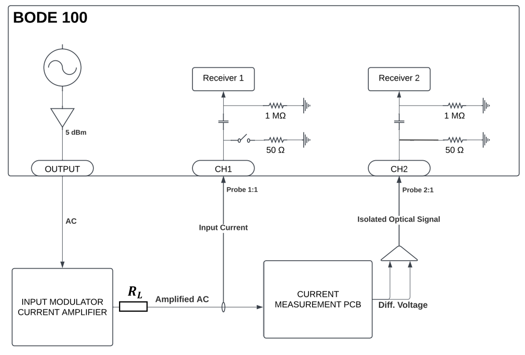
Fig. 289 Figure: Block diagram of AC impedance test setup using Bode 100, Spitzenberger APS 1000 (Input Modulator Current Amplifier), load resistor and optical probes.#
Configuration Details#
Bode 100 output is set to X dBm and connected to APS 1000 input.
APS 1000 amplifies the AC signal and injects current into the current measurement PCB.
Output Differential voltage generated by the op-amp is measured via MOIP350P probe and sent to CH2.
Current Probe CP1003B is connected to CH1 for sensing injected current.
Bode 100 computes gain \(G = \frac{V_{\text{CH2}}}{V_{\text{CH1}}}\) and converts to impedance.
Note
The Spitzenberger APS 1000 must be set to external source mode, where it amplifies the signal from the Bode 100 output rather than generating its own. Ensure the AC IN input of the APS 1000 is connected to the Bode 100 output, and internal signal generation is disabled. This setup allows the Bode 100 to control the frequency sweep, while the APS 1000 injects the corresponding amplified current into the analog current measurement card.
Probe Ratio Settings#
CH1 (Current Probe): - Micsig CP1003B set to 5 A mode with a sensitivity of 1 V/A. Bode 100 CH1 probe ratio is set to 1:1, which means that the current probe outputs 1 V for every 1 A. 1:1 ratio ensures direct interpretation without scaling.
CH2 (Voltage Probe): - Micsig MOIP350P OP200-3 configured with 20 dB attenuation, equivalent to a 2:1 attenuation ratio (datasheet). Bode 100 CH2 probe ratio must be set to 2:1 for Bode 100 to account for the probe’s attenuation so it correctly scales the measured voltage.
Note
The Bode 100 interprets probe signals based on the configured ratio:
1:1 → No scaling
X:1 → Signal is internally multiplied by X
Therefore, if the voltage probe attenuates the signal by a factor of 2 (when 20 dB setting is chosen on the probe), the ratio must be set to 2:1 in Bode 100 for proper compensation.
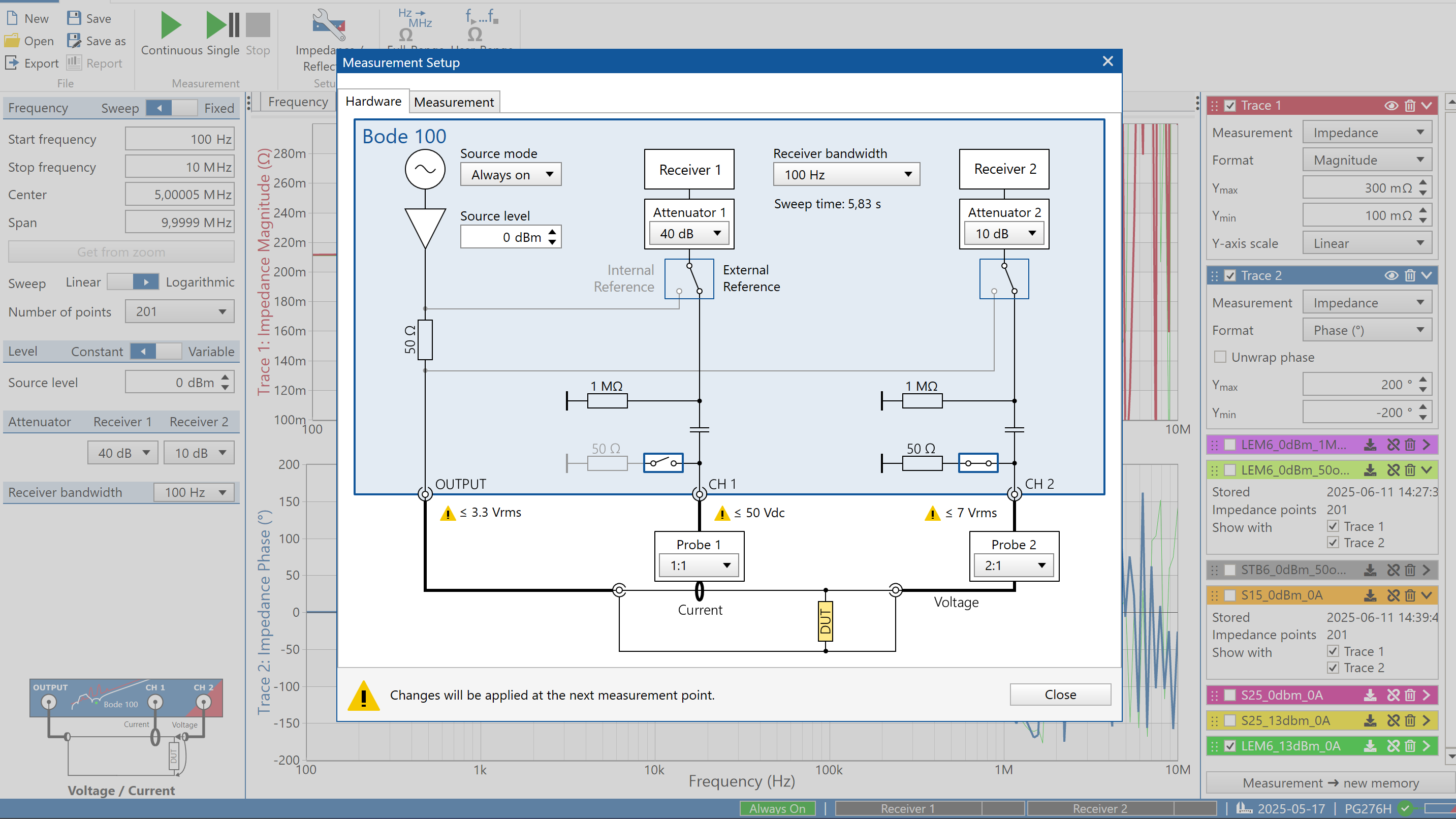
Fig. 290 Figure: Test Setup of Bode100#
Notes on Bode 100 Configuration#
The source level of the Bode 100 output is defined in dBm, which expresses signal power relative to 1 mW into a 50 Ω load. To calculate the output voltage amplitude, use:
For input impedance of 50 Ω in AC IN of Bode 100, this simplifies to:
For Range = 26.4 A_peak (setting in APS1000), this yields the following output current amplitudes:
At 0 dBm: \(V_{\mathrm{RMS}} = 0.224\,\mathrm{V}\) (\(V_{\mathrm{peak}} \approx 0.316\,\mathrm{V}\)), resulting in \(I_{\mathrm{peak}} \approx 1.67\,\mathrm{A}\) after amplification.
At 12 dBm: \(V_{\mathrm{RMS}} = 0.708\,\mathrm{V}\) (\(V_{\mathrm{peak}} \approx 1.000\,\mathrm{V}\)), resulting in \(I_{\mathrm{peak}} \approx 5.30\,\mathrm{A}\) after amplification.
This value is fed to the APS 1000, which amplifies it according to the selected Range, resulting in the actual test input current.
Notes on APS 1000 Current Source Behaviour#
The Spitzenberger APS 1000 operates similarly to a linear regulator: it regulates the voltage based on the input signal from the Bode 100 and generates a corresponding current based on the selected I-Range limit.
The APS 1000 settings -> Amplifier Control -> Limit includes a Range setting that defines the effective gain of the current amplifier. The analog input range of AC IN of APS 1000 is +-5V. The Range setting divided by 5V results in the gain:
When set to a higher range (e.g. 26.4 A_peak), the gain is 26.4 A_peak / 5V = 5.28 A/V.
When set to a lower range (e.g. 3 A_peak), the gain is 3 A_peak / 5V = 0.60 A/V.
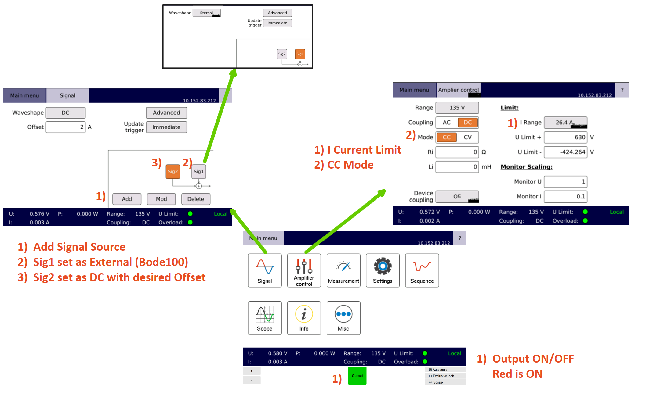
Fig. 291 Figure: Test Setup of Spitzenberger APS 1000 for Range configuration and optional DC Offset#
Limitations of APS 1000 Current Source#
The current output of the Spitzenberger APS 1000 current amplifier is frequency-dependent, which directly affects the accuracy of AC impedance measurements in this test system. According to the APS 1000 datasheet:
Large signal bandwidth (full-scale output current): DC to 10 kHz (-3 dB cutoff)
Small signal bandwidth (10% of full scale): DC to 50 kHz (-3 dB cutoff)
This means that the output current starts to roll off above 10 kHz for high-amplitude signals and they start to roll of above 50 kHz for low-amplitude excitation.
Warning
Impedance measurements above 30-50 kHz become unreliable due to reduced current output from the APS 1000. In the impedance calculation, a reduced current value leads to an overestimated impedance, which make the impedance go high after this frequency range.
Additional Limitations of the Test Setup#
dv/dt immunity of the sensors is not tested directly within the test system. The Bode 100 setup applies sinusoidal current excitation, which lacks fast voltage transients. Therefore it does not replicate high dv/dt conditions that are present in inverter switching events. As a result, any conclusions regarding dv/dt performance must be drawn only from the sensor datasheets or related application notes.
Real-world AC test Setup#
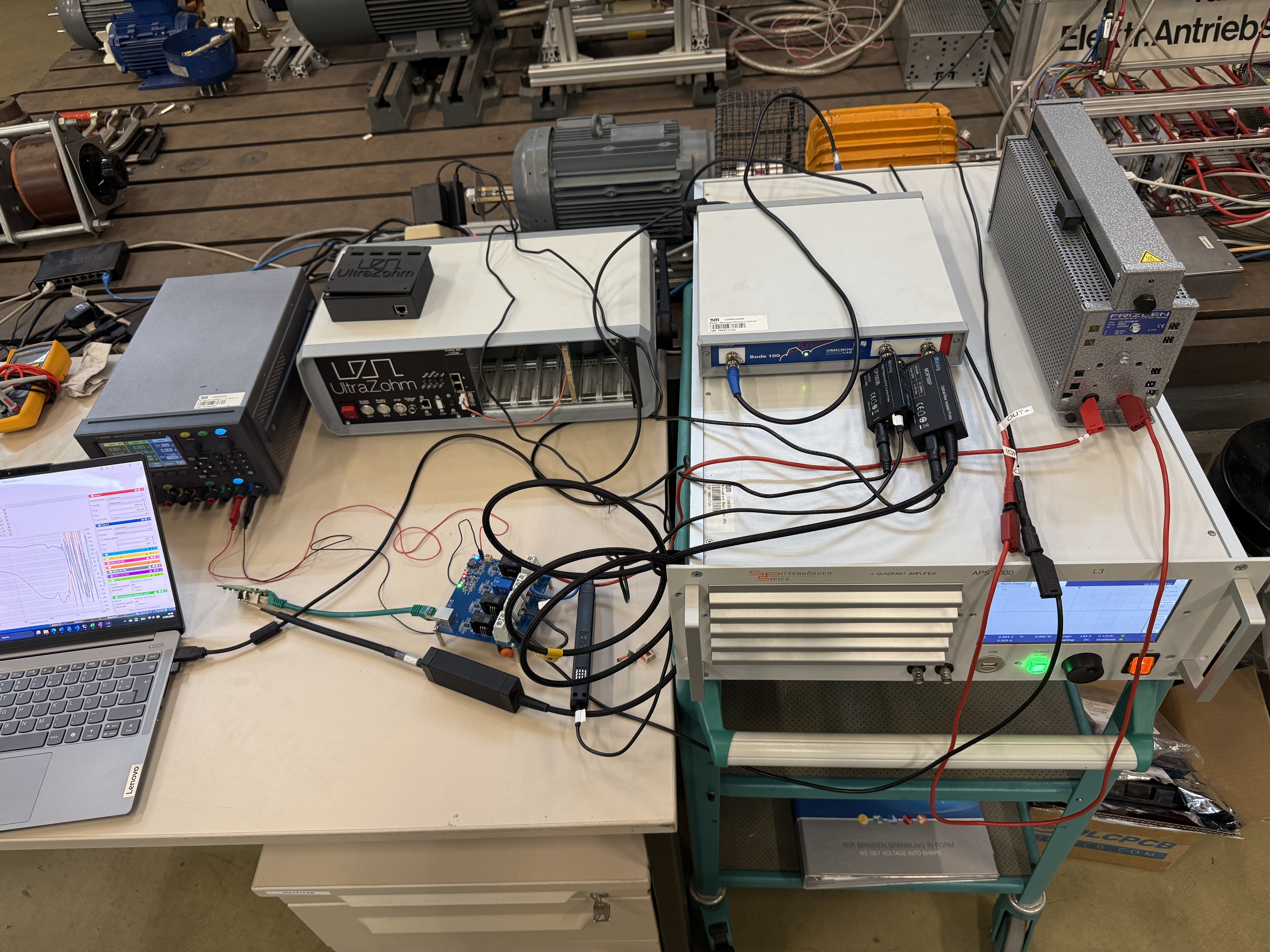
Fig. 292 Real-world AC test setup in the lab, showing the configured equipment and wiring.#
Purpose of the Series Load Resistor#
A series 68 Ω load resistor is connected between the output of the Spitzenberger APS 1000 current amplifier and the current input of the PCB. As mentioned earlier, the APS 1000 operates similarly to a linear voltage regulator, which results in internal power dissipation. To avoid excessive internal heat generation, the external load resistor shares this power dissipation, reducing thermal stress on the amplifier.
Therefore, the load resistor serves two purposes:
It acts as a voltage drop element for power dissipation
It protects the internal current modulator stage of the APS 1000 from thermal overload